
Filtering chamber for gas turbines and method of maintenance thereof

Active Publication Date: 2016-04-07
NUOVO PIGNONE TECH SRL
View PDF12 Cites 12 Cited by
  • Summary
  • Abstract
  • Description
  • Claims
  • Application Information

AI Technical Summary

Benefits of technology

The patent text describes a filter system for gas turbines that reduces the risk of damage or contamination when replacing filter components. The system includes two filters, a first filter arrangement with lower collection efficiency, a second filter arrangement with higher efficiency, and a first guard filter arrangement with lower efficiency between the two filter arrangements. The first guard filter arrangement prevents dirt from reaching the second filter arrangement during operation. The technical effect of this system is to allow for the replacement of filter components without damaging or contaminating the downstream filter arrangement, while also maintaining efficient filtration.

Problems solved by technology

Although the dust concentration in the atmosphere is normally very low, a gas turbine requires such a large quantity of air to operate that even a medium sized heavy duty or aero-derivative gas turbine could ingest some hundreds of kilograms of dust per year if no efficient filtering systems are provided.
These surfaces can be roughened by corrosion and erosion; while the ingestion of substances, which adhere to the surfaces (fouling) will modify their shapes.
Furthermore, the ingestion of contaminants may generate high temperature corrosion, plugging of cooling passages and particle fusion on the high temperature sections of the gas turbine.
These highly performing filters are extremely expensive and, due to their collection efficiency, must be provided with efficient upstream coarse filtering arrangements, to prevent clogging thereof.
Turbine shut down, on the other hand, causes serious economic losses.

Method used


Image

  • Filtering chamber for gas turbines and method of maintenance thereof
  • Filtering chamber for gas turbines and method of maintenance thereof
  • Filtering chamber for gas turbines and method of maintenance thereof

Examples


Embodiment Construction

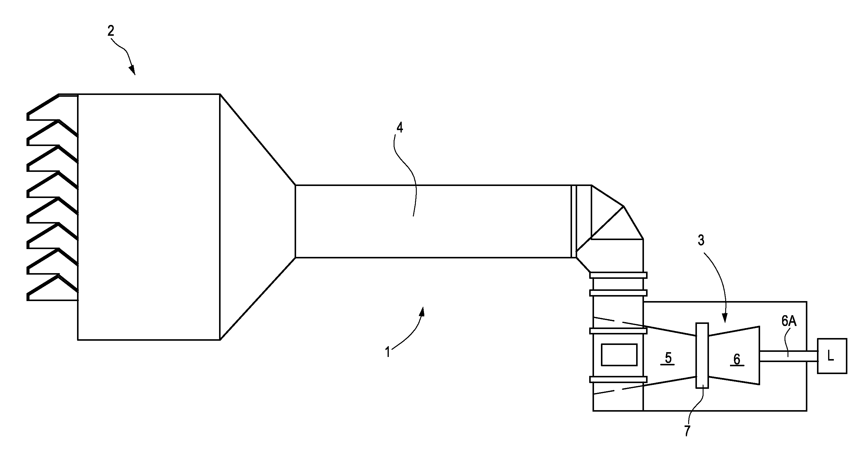
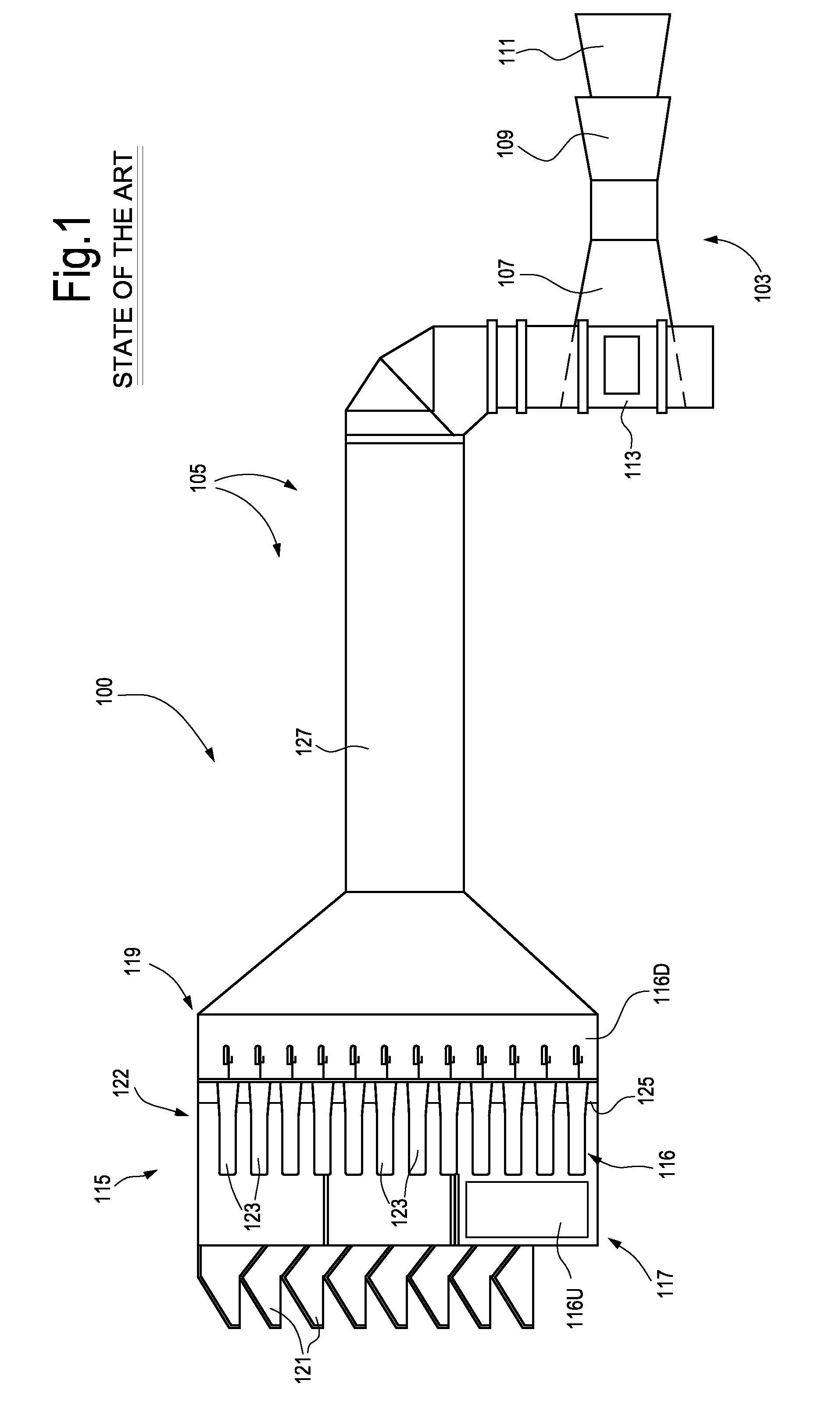
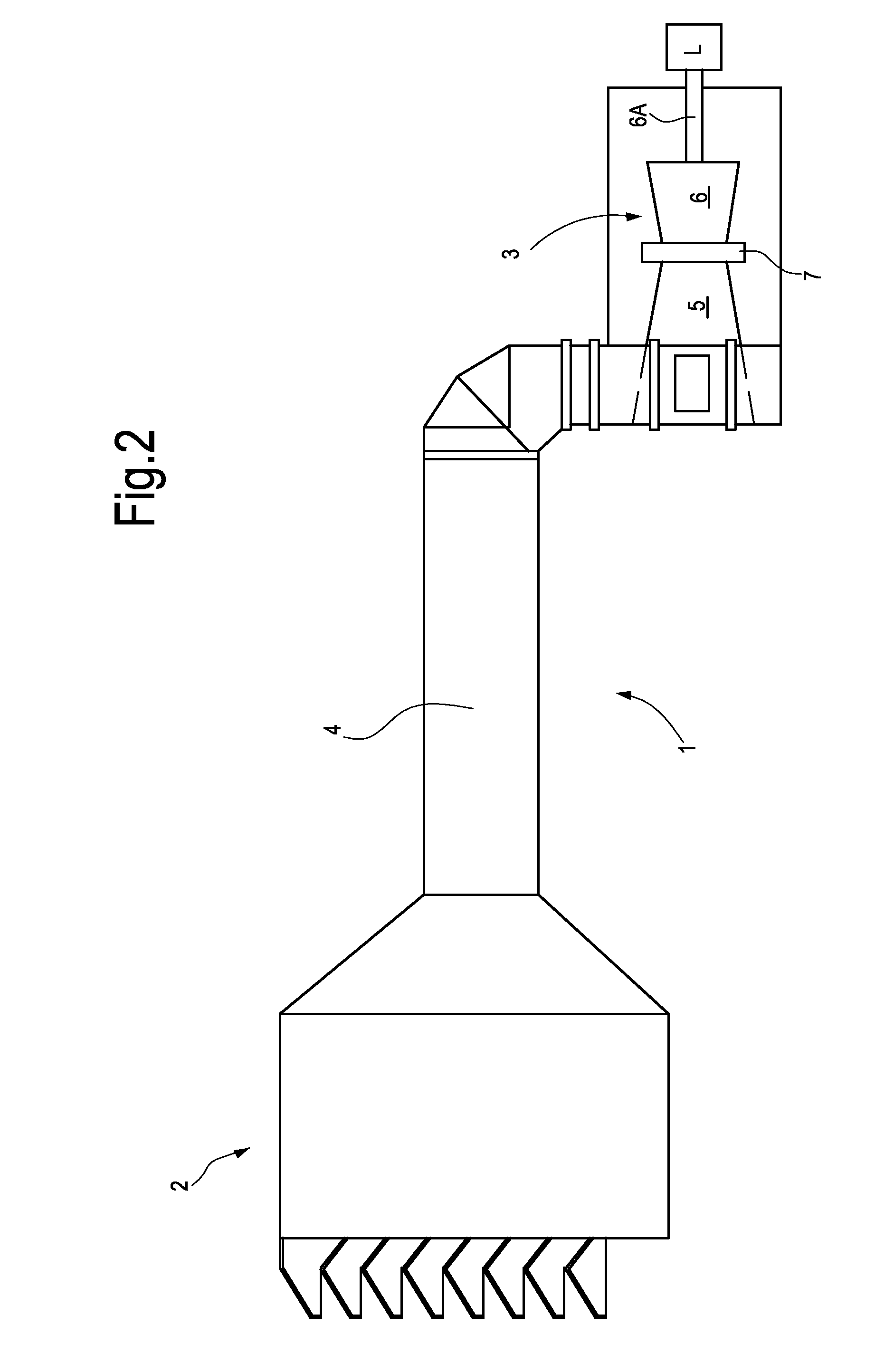
[0025]The following detailed description of the exemplary embodiments refers to the accompanying drawings. The same reference numbers in different drawings identify the same or similar elements. Additionally, the drawings are not necessarily drawn to scale. Also, the following detailed description does not limit the invention. Instead, the scope of the invention is defined by the appended claims.

[0026]Reference throughout the specification to “one embodiment” or “an embodiment” or “some embodiments” means that the particular feature, structure or characteristic described in connection with an embodiment is included in at least one embodiment of the subject matter disclosed. Thus, the appearance of the phrase “in one embodiment” or “in an embodiment” or “in some embodiments” in various places throughout the specification is not necessarily referring to the same embodiment(s). Further, the particular features, structures or characteristics may be combined in any suitable manner in one...


PUM

PropertyMeasurementUnit
Flow rateaaaaaaaaaa
Volumeaaaaaaaaaa
Efficiencyaaaaaaaaaa

Abstract

A filter system for filtering intake air of a gas turbine, comprising a first filter arrangement and a second filter arrangement, located downstream from the first filter arrangement and having a higher collection efficiency than the first filter arrangement. Furthermore, a guard filter arrangement, having a lower collection efficiency than the first filter arrangement, is located between the first filter arrangement and the second filter arrangement.

Description

TECHNICAL FIELD[0001]The present disclosure relates to filtering chambers and methods for maintaining the same. More specifically, the present disclosure relates to filtering chambers for gas turbines.BACKGROUND[0002]Gas turbines both for electric generation and mechanical drive applications operate in a variety of environments. In order to adapt the machines to the environment where they have to operate and realize their full potential in terms of performance and reliability, it is necessary to treat the air that they consume. Although the dust concentration in the atmosphere is normally very low, a gas turbine requires such a large quantity of air to operate that even a medium sized heavy duty or aero-derivative gas turbine could ingest some hundreds of kilograms of dust per year if no efficient filtering systems are provided.[0003]The efficiency of the axial compressor of a gas turbine is a direct function of the smoothness of the rotating and stationary blade surfaces and the sh...

Claims


Application Information

Patent Timeline
IPC IPC(8): B01D46/00F02C7/052F02C7/055
CPCB01D46/0026B01D46/0023B01D46/0068B01D46/008F05D2230/70F02C7/052F05D2220/32F05D2230/60F02C7/055B01D2279/60B01D46/71B01D46/62B01D46/24B01D46/645B01D46/88
Inventor SANTINI, MARCOMARCHETTI, GIORGIO
Owner NUOVO PIGNONE TECH SRL
Learn More