Cooling Structure of Heating Element and Power Conversion Device

Active Publication Date: 2016-03-31
HITACHI IND PROD LTD
View PDF14 Cites 4 Cited by
  • Summary
  • Abstract
  • Description
  • Claims
  • Application Information

AI Technical Summary

Benefits of technology

The present invention is a cooling structure for a heating element and a power conversion device. It is designed to prevent breakage of the heating element while cooling it. The cooling structure includes a heating element with cooling surfaces and heat receiving plates with holes for the cooling fins. A cooler with clamps presses the heating element and the heat receiving plate to cool them further. Distance between the clamps is secured to prevent damage to the heating element. The power conversion device includes multiple semiconductor devices with cooling surfaces, heat receiving plates, clamps, heat dissipating fins, and a heat pipe for cooling the heat receiving plates. The cooling wind is fed to the fins from the opposite side of the heating element. The invention allows for efficient cooling of the heating element while preventing damage.

Problems solved by technology

However, a heating element that has been originally designed as a water-cooled one does not assume application of a strong pressing force thereto because the heating element does not assume attachment of an external cooling fin thereto while having small pin fins (fins each projecting in the form of a pin) or the like.
Accordingly, when attempting to simply attach an external cooling fin to the heating element by bolting or the like, there is a possibility that the heating element is broken.

Method used


Image

  • Cooling Structure of Heating Element and Power Conversion Device
  • Cooling Structure of Heating Element and Power Conversion Device
  • Cooling Structure of Heating Element and Power Conversion Device

Examples


modified examples

[0081]The present invention is not limited to the above embodiments, and can be variously modified, for example, as follows.

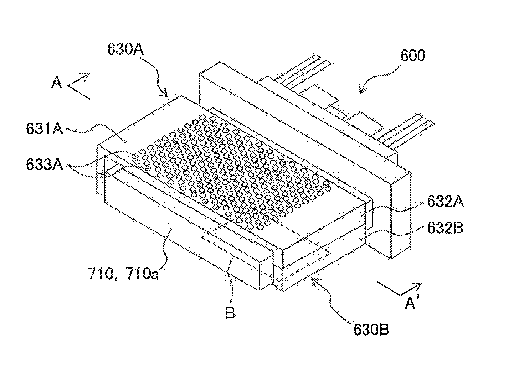
[0082](1) Through-holes to be formed in the heat receiving spacers 630A, 630B are not limited to ones in the embodiments, and can be changed to ones having various shapes and sizes as long as they are, in short, through-holes to allow the pin fins 762 to be movably inserted thereinto. For example, as shown in FIG. 18, rectangular through-holes 640A may be formed at positions corresponding to each pin fin 762A, in the heat receiving spacers 630A. In this case, even if a length of one side of the rectangular through-hole 640A is the same as the diameter of the circular through-hole 633A (see FIG. 8) in the above embodiments, an area of the through-hole 640A can be increased resulting in an advantage of further facilitating work to attach the heat receiving spacer 630A to the double-sided cooling power module 600.

[0083](2) Moreover, each of through-holes to be for...


PUM


Abstract

A cooling structure of a heating element includes: the heating element having at least one cooling surface from which a plurality of pin fins project; a heat receiving plate which has a shape complying with the cooling surface and in which holes are formed at positions facing each pin fin, each pin fin being movably inserted into the holes; a cooler which has a pair of clamping members that sandwich therebetween the heating element and the heat receiving plate while pressing the heating element and the heat receiving plate, and which cools the heat receiving plate; and a space securing part which is provided on the heat receiving plate and suppresses a distance between the pair of clamping members so as not to apply a pressing force by the clamping members to the heating element.

Description

CROSS-REFERENCE TO RELATED APPLICATION[0001]This application is based upon and claims the benefit of priority to the Japanese Patent Application No.2014-198049, filed on Sep. 29, 2014, the entire contents of which are incorporated herein by reference.BACKGROUND OF THE INVENTION[0002]1. Field of the Invention[0003]The present invention relates to a cooling structure of a heating element and a power conversion device.[0004]2. Description of the Related Art[0005]Patent Document 1 (Japanese Patent Application Publication No.2013-073964) discloses in paragraph [0001]“The invention relates to a power module that has good heat dissipation and reliability”, and in paragraph [0011]“A heat dissipating portion 307A is provided on one of two surfaces of the flat case that have wide areas and face each other, and a heat dissipating portion 307B is provided on the other surface. The heat dissipating portion 307A and the heat dissipating portion 307B function as heat dissipating wails of the modul...

Claims


Application Information

Patent Timeline
IPC IPC(8): H01L35/04H01L35/32H02M1/00
CPCH01L35/04H01L35/32H01L23/3677H01L23/427H01L2924/0002H01L2924/00H10N10/17H10N10/81H01L23/40H05K7/20336H05K7/20409H05K7/209
Inventor MATSUMOTO, DAISUKEMIMA, AKIRAKAWASHIMA, TETSUYAMABUCHI, YUUICHIHATTORI, YUKIOKAMIZUMA, HIROSHIMIYAGAWA, RYOUHEIICHIKAWA, TOMONORI
Owner HITACHI IND PROD LTD
Why Eureka
Try Eureka