Multi-Panel Display Device

Active Publication Date: 2017-12-28
LG DISPLAY CO LTD
View PDF4 Cites 5 Cited by
  • Summary
  • Abstract
  • Description
  • Claims
  • Application Information

AI Technical Summary

Benefits of technology

The present disclosure is about a multi-panel display device that solves problems with existing technologies. The device improves image continuity, prevents optical member collision, and prevents rainbow phenomenon.

Problems solved by technology

However, in the case of the multi-panel display device, a bezel region of each of the plurality of display devices reduces a continuity of image.

Method used


Image

  • Multi-Panel Display Device
  • Multi-Panel Display Device
  • Multi-Panel Display Device

Examples


first embodiment

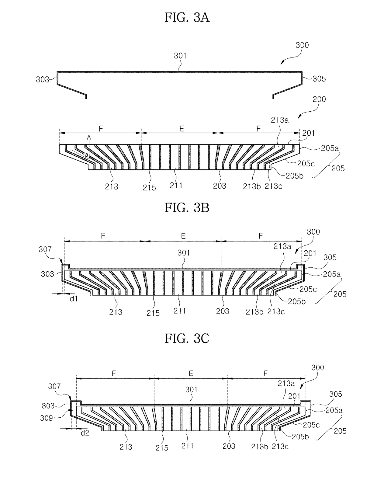
[0066]FIGS. 3A to 3C are cross-sectional views illustrating a entire-surface type optical member and a protection film according to the

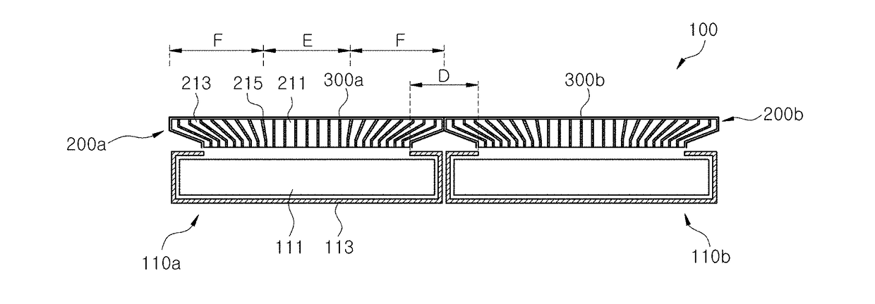
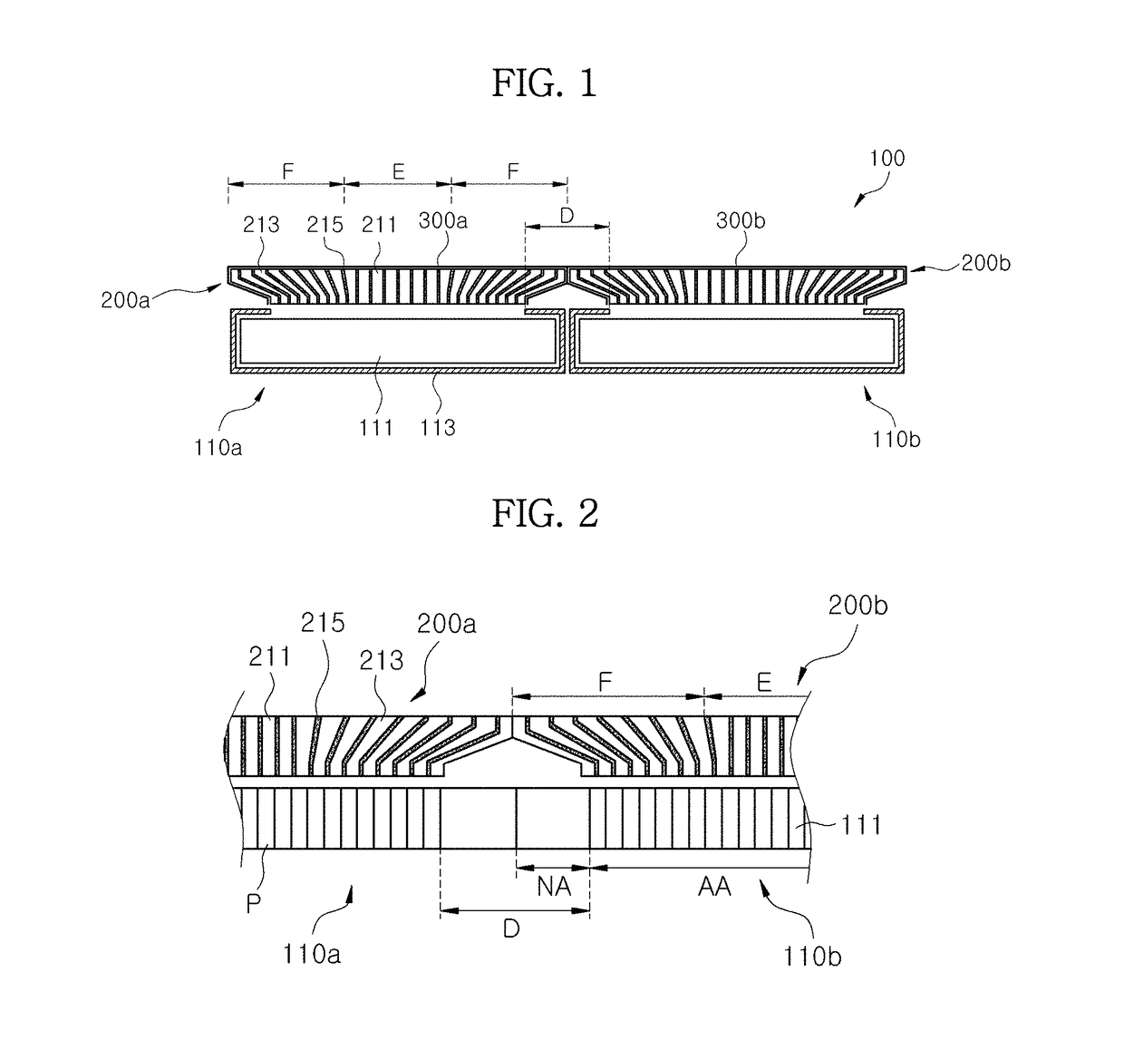
[0067]The entire-surface type optical member 200 is located on each of the display devices (110a and 110b of FIG. 2) when fabricating the multi-panel display device (100 of FIG. 1) with the display devices (110a and 110b of FIG. 2) connected to each other.

[0068]The entire-surface type optical member 200 is defined to be divided into a non-enlarging region E at a center portion and an enlarging region F at a peripheral portion surrounding the non-enlarging region E. The plurality of optical fibers 211 and 213 are defined to be divided into a plurality of first optical fibers 211 located at the non-enlarging region E and a plurality of second optical fibers 213 located at the enlarging region F.

[0069]A shape of the entire-surface type optical member 200 is described in detail as follows. The entire-surface type optical member 200 includes a first top s...

second embodiment

[0100]FIGS. 6A to 6D are cross-sectional views illustrating a frame type optical member and a protection film according to the

[0101]FIG. 7A is a view showing an experiment result that a rainbow phenomenon happens due to a chromatic dispersion, and FIG. 7B is a view showing an experimental result that a rainbow phenomenon is concealed by a protection film of the second embodiment.

[0102]Referring to FIGS. 6A to 6D, the frame type optical member 400 is located on each of the display devices (110a and 110b of FIG. 5) when fabricating the multi-panel display device (100 of FIG. 4) with the display devices (110a and 110b of FIG. 5) connected to each other.

[0103]The optical member 400 is formed in a frame type of a ring shape. A shape of the frame type optical member 400 is described in detail as follows. The frame type optical member 400 is configured corresponding to a portion of a periphery of the display panel (111 of FIG. 5) and the bezel region (D of FIG. 5) of each of the display de...


PUM


Abstract

A multi-panel display device includes a first display device including a first display region and a first non-display region surrounding the first display region; a first optical member located on the first display device and including optical fibers; and a first protection film covering an outside of the first optical member.

Description

CROSS REFERENCE TO RELATED APPLICATIONS[0001]The present application claims the priority benefit of Korean Patent Application No. 10-2016-0080080 filed in Republic of Korea on Jun. 27, 2016, which is hereby incorporated by reference in its entirety for all purposes as if fully set forth herein.BACKGROUNDField of the Invention[0002]The present disclosure relates to a multi-panel display device in which a plurality of display devices are connected to each other, and more particularly, to a multi-panel display device to reduce an image disconnection at a bezel region, which is a connection portion between display devices, happens.Discussion of the Related Art[0003]Facing information society, display field of processing and displaying a massive amount of information has been rapidly advanced, and accordingly, various display devices have been developed and used.[0004]As display devices, liquid crystal display devices (LCD), plasma display panel devices (PDP), field emission display devi...

Claims


Application Information

Patent Timeline
IPC IPC(8): G06F3/14G02F1/1343G09G3/36G02F1/1333G02F1/1335
CPCG06F3/1446G09G3/3666G02F1/133514G02F1/13336G02F1/1343G02F1/1345G02F1/13454G02F1/13458G09G3/20G09G2300/026G09G2300/0426G09G2310/0232G02F1/13456G09F9/3026G09G2360/04
Inventor CHIN, MI-HYUNGYANG, SEUNG-SOORHIM, JU-SANG
Owner LG DISPLAY CO LTD
Why Eureka
Try Eureka