
Systems, intraocular lenses, and methods for treatment of posterior capsule opacification

a technology of intraocular lenses and opacification, which is applied in the field of intraocular lens designs and methods of treatment for posterior capsule opacification, can solve the problems of reduced visual acuity, decreased visual acuity, poor visual acuity at close distances, etc., and achieves the effect of preventing or substantially eliminating damage to iols and more robustly resisting damage from pco treatments

Inactive Publication Date: 2016-03-31
DEBOER CHARLES +4
View PDF0 Cites 1 Cited by
  • Summary
  • Abstract
  • Description
  • Claims
  • Application Information

AI Technical Summary

Benefits of technology

This patent is about a technique to prevent damage to IOLs (the lenses used in eye surgery) caused by a process called PCO. The invention suggests various methods to either treat or prevent PCO, including opening the posterior lens capsule and moving the IOL away from it before PCO formation. The technique ensures that the optical axis of the eye is not degraded due to PCO, which is caused by cell migration. Overall, the patent aims to make PCO treatment safer and more effective for IOL implantation.

Problems solved by technology

While some lens opacities are small and require no treatment, others may be large enough to block significant fractions of light and decrease the visual acuity.
However, because the focal distance is not adjustable following implantation of the monofocal IOL, patients implanted with such lenses can no longer focus on objects at a close distance (e.g., less than twenty-five centimeters); this results in poor visual acuity at close distances.
PCO decreases the amount of light that reaches the retina, causing a decrease in visual acuity.
When applied to the posterior capsule, the laser energy produces thermal and mechanical damage thereto.
While such laser-based treatments have a reasonably high success rate, in some cases, the laser beam may damage the IOL, leading to a decrease in visual acuity and contrast and causing glare for the patient.
Such damage may occur due to incorrect focusing of the laser energy.
In some cases, however, the IOL is sufficiently close to the posterior capsule that even laser light correctly focused on the posterior capsule may damage the IOL.
Mild damage may be characterized as small pits with raised smooth edges, while moderate damage may include deeper pits and / or large craters or small cracks, and severe damage may include severe cracking or crevice formation into the optic.

Method used


Image

  • Systems, intraocular lenses, and methods for treatment of posterior capsule opacification
  • Systems, intraocular lenses, and methods for treatment of posterior capsule opacification
  • Systems, intraocular lenses, and methods for treatment of posterior capsule opacification

Examples


Embodiment Construction

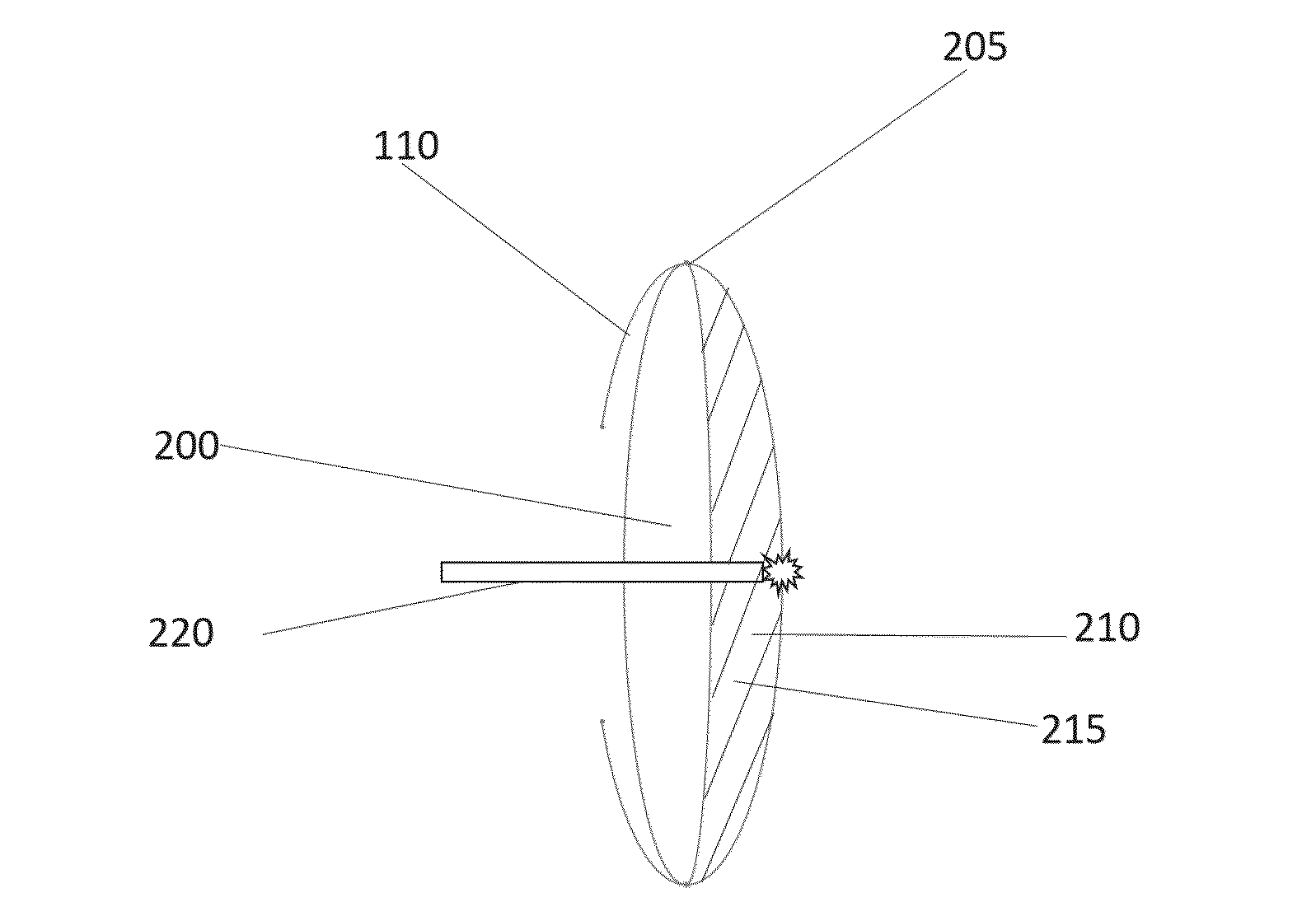
[0047]Embodiments of the present invention feature PCO treatments in which the IOL and the posterior lens capsule are spaced apart prior to removing the posterior lens capsule. Refer to FIG. 2A, which depicts a conformally fitting IOL 200 implanted in a lens capsule 110. As shown, the lens capsule 110 has an anterior surface 110a, a posterior surface 110p, and a peripheral surface 110s between anterior surface 110a and posterior surface 110p. IOL 200 has an anterior optical surface 200a facing the anterior surface 110a of the lens capsule 110, a posterior optical surface 200p facing the posterior surface 110p of the lens capsule 110, and a peripheral sealing portion 205 disposed between the anterior optical surface 200a and the posterior optical surface 200p. Due to the conformal fit of the lens, the peripheral sealing portion 205 of the IOL 200 sealingly contacts (i.e., interfaces with) lens capsule 110 (e.g., the peripheral surface 110s), thereby creating a compartment 210 that is...


PUM


Abstract

In various embodiments, ocular treatment systems, intraocular lenses, and treatment methods are utilized for the treatment or prevention of posterior capsule opacification of the eye by, for example, targeting portions of the posterior lens capsule for ablation while minimizing damage to implanted intraocular lenses.

Description

RELATED APPLICATIONS[0001]This application claims the benefit of and priority to U.S. Provisional Patent Application No. 62 / 056,950, filed Sep. 29, 2014, and U.S. Provisional Patent Application No. 62 / 066,134, filed Oct. 20, 2014, the entire disclosure of each of which is hereby incorporated herein by reference.TECHNICAL FIELD[0002]In various embodiments, the present invention relates to intraocular lens designs and methods of treatment for posterior capsule opacification.BACKGROUND[0003]The crystalline lens of a human's eye refracts and focuses light onto the retina. Normally the lens is clear, but it can become opaque (i.e., when developing a cataract) due to aging, trauma, inflammation, metabolic or nutritional disorders, or radiation. While some lens opacities are small and require no treatment, others may be large enough to block significant fractions of light and decrease the visual acuity. In such cases, surgical removal of the cataract is often necessary.[0004]Conventionally...

Claims


Application Information

Patent Timeline
IPC IPC(8): A61F2/16A61F9/007A61F9/008
CPCA61F2/16015A61F9/00802A61F2009/00887A61F2002/16901A61F2009/0087A61F9/00745A61F2/1613A61F2002/009
Inventor DEBOER, CHARLESMAGALHAES, RIBEIRO, RAMIROHUMAYUN, MARK, S.TAI, YU-CHONGCAFFEY, SEAN
Owner DEBOER CHARLES
Learn More