Electronic device
a technology of electronic devices and components, applied in the direction of electrical apparatus casings/cabinets/drawers, casings with connectors and pcbs, support structure mounting, etc., can solve the problems of screw member loosening, noise generation, expansion and/or contraction of printed circuit boards, etc., to prevent the loosening of screw members
- Summary
- Abstract
- Description
- Claims
- Application Information
AI Technical Summary
Benefits of technology
Problems solved by technology
Method used
Image

Examples
first embodiment
[0048]A structure of an electronic device 10 according to a first embodiment of the present disclosure will be explained.
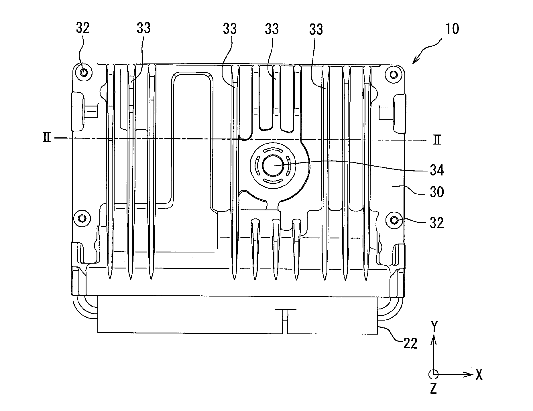
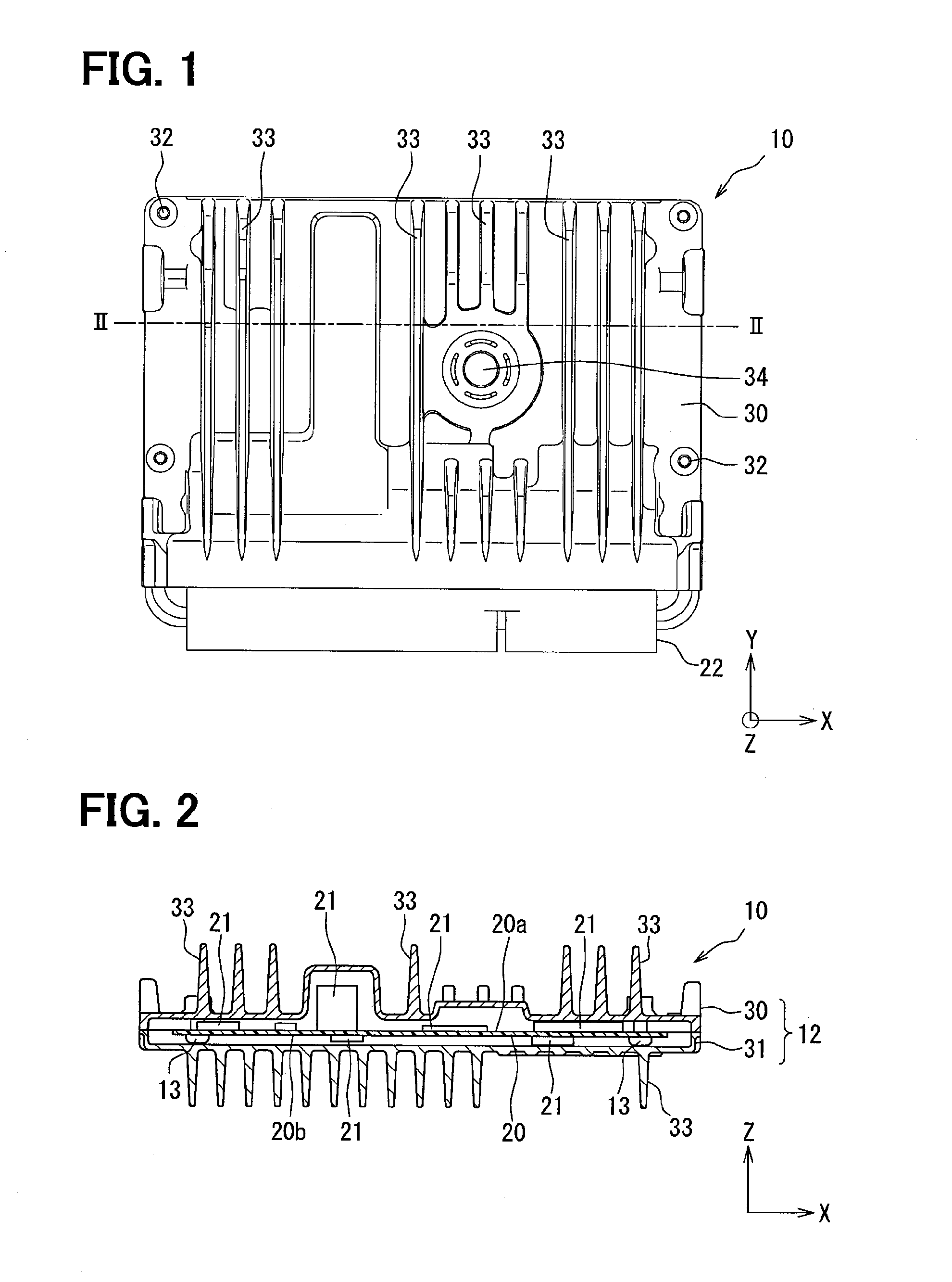
[0049]The electronic device 10 shown in FIGS. 1 to 3 is an electronic control unit (hereinafter, the ECU) for an engine of an automotive vehicle. The electronic device 10 has a water-proof structure.
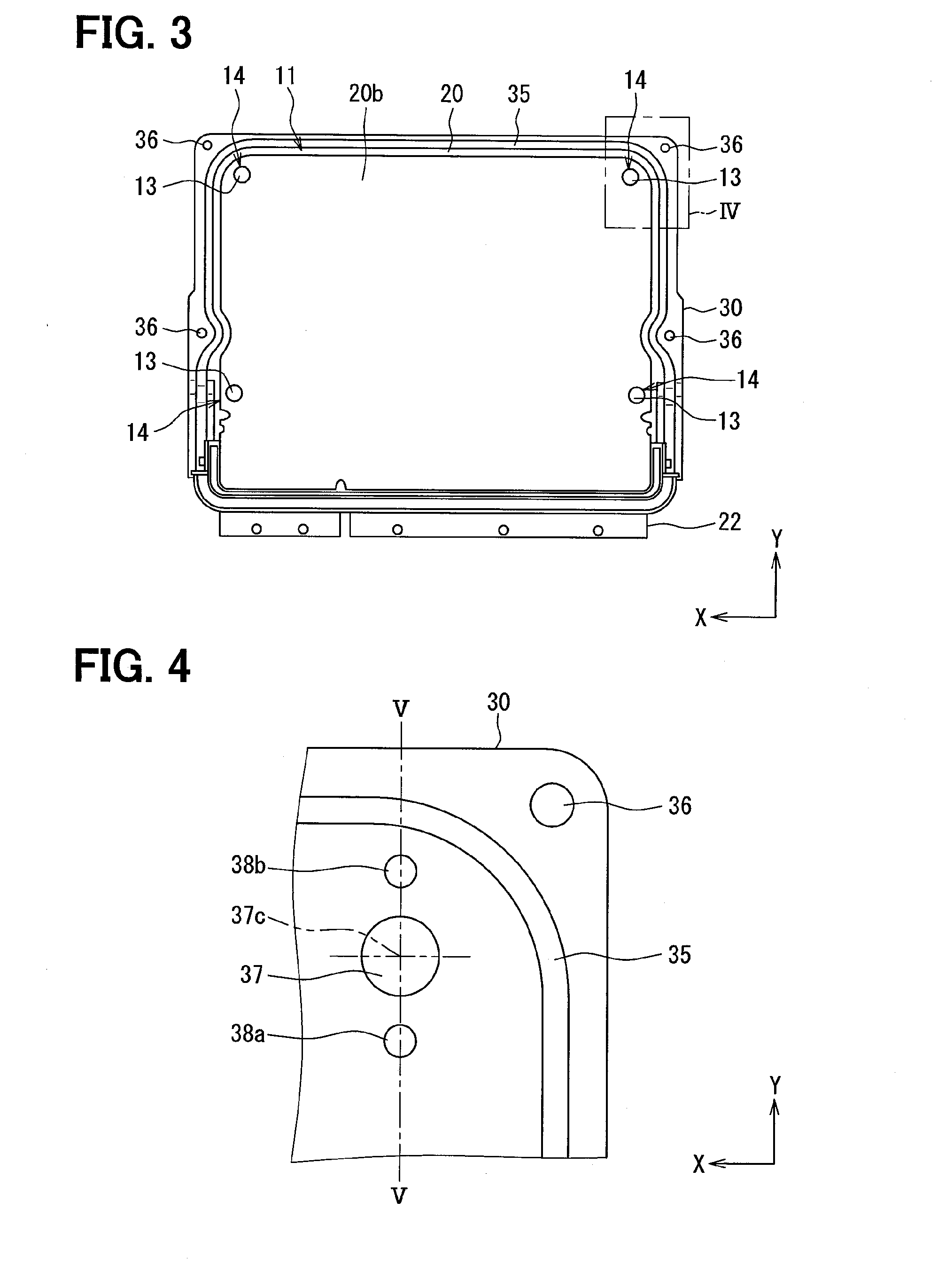
[0050]The electronic device 10 is composed of a circuit board assembly 11, a housing 12 for accommodating the circuit board assembly 11, multiple screw members 13 for fixing the circuit board assembly 11 to the housing 12 and so on.
[0051]The circuit board assembly 11 is composed of a base plate 20, multiple electronic components 21 and so on. The base plate 20 is composed of a printed circuit board, wherein electric wiring patterns are formed in and / or on an electrical insulating plate made of resin, ceramic material or the like. The multiple electronic components 21 are mounted to the base plate 20, so that electric circuits are formed by the electric wiring patterns ...
second embodiment
[0085]A second embodiment of the present disclosure will be explained with reference to FIGS. 7 and 8. Explanation for those portions of an electronic device according to the second embodiment, which are the same to those of the first embodiment, will be omitted.
[0086]In the present embodiment, two projections 42a and 42b are formed in the screw member 13, so that the screw member 13 is brought into contact with the second board surface 20b of the base plate 20 at two contacting points in each screw-fixing portion 14. As shown in FIGS. 7 and 8, a first projection 42a and a second projection 42b, each of which extends from the screw head 40 in a direction to the base plate 20, are formed on the contact-side surface portion 40a of the screw head 40. The projections 42a and 42b formed in the same screw-fixing portion 14 are arranged in a symmetric manner with respect to a center axis 13c of the screw member 13.
[0087]In a condition that the screw shaft 41 is inserted and screwed into th...
first modification
(First Modification)
[0092]A screw member having a washer may be also used in the second embodiment. In such a case, the projections 42a and 42b are formed on the washer. As shown in FIG. 9, which shows a modification of the second embodiment, the screw member 13 has a plain washer 43, which is integrally connected to the screw head 40 and / or the screw shaft 41. The projections 42a and 42b are formed on a contact-side surface portion 43a of the plain washer 43, which is opposed to the second board surface 20b of the base plate 20. The plain washer 43 may be formed as an independent member from the screw member 13 (a separate member from the screw head 40 and the screw shaft 41).
PUM
 Abstract
Description
Claims
Application Information
 - R&D
- Intellectual Property
- Life Sciences
- Materials
- Tech Scout
- Unparalleled Data Quality
- Higher Quality Content
- 60% Fewer Hallucinations
Browse by: Latest US Patents, China's latest patents, Technical Efficacy Thesaurus, Application Domain, Technology Topic, Popular Technical Reports.
© 2025 PatSnap. All rights reserved.Legal|Privacy policy|Modern Slavery Act Transparency Statement|Sitemap|About US| Contact US: help@patsnap.com