
Depth of field in an imaging system

a technology of depth of field and imaging system, which is applied in the field of improving the depth of field in the imaging system, can solve the problems of reducing the camera's performance in low light, reducing the shutter speed by a factor of 4 or 8 and the limitation that exists in all optical systems used in cameras today

Inactive Publication Date: 2016-03-24
DUAL APERTURE INT
View PDF9 Cites 2 Cited by
  • Summary
  • Abstract
  • Description
  • Claims
  • Application Information

AI Technical Summary

Benefits of technology

The invention provides a method of capturing an image using two different apertures to improve the depth of field and sharper pictures. The method allows a fixed focus lens to have a wider aperture in lower light situations, while still providing a relatively wide aperture for increased optical performance and reducing the cost of the lens required for the same performance. The two exposures can be simultaneous or sequential, and the sensor can use filters to access sharp image information. The method can be easily adapted to different aperture configurations using thin film technology and can include adjustable apertures or tunable filters.

Problems solved by technology

A limitation that exists in all optical systems used in cameras today is the tradeoff between aperture and the depth of field (DOF).
This tradeoff reduces the camera's performance in low light situations typically reducing the shutter speed by a factor of 4 or 8.
Further, in low light applications a wide aperture is required, which results in a loss of DOF.
Wide aperture lenses require greater precision for optical performance and are therefore expensive.
Moreover, as the focus stacking requires multiple images taken at subsequent moments in time this technique is sensitive to motion blur.
The aperture splitting mirror however is complex to fabricate and produces high optical aberrations.
Moreover, implementation of such splitting mirror in a camera requires a relative complex optical system which requires precise alignment.

Method used


Image

  • Depth of field in an imaging system
  • Depth of field in an imaging system
  • Depth of field in an imaging system

Examples


Embodiment Construction

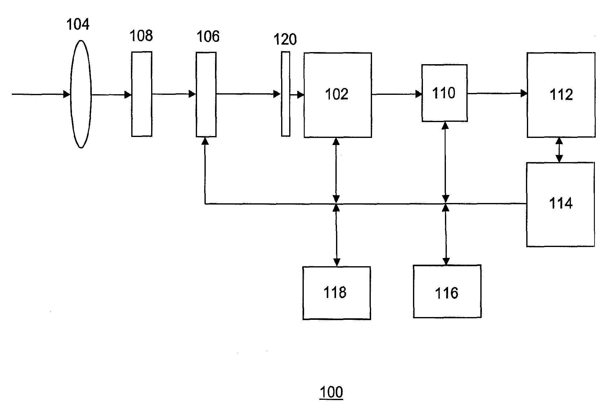
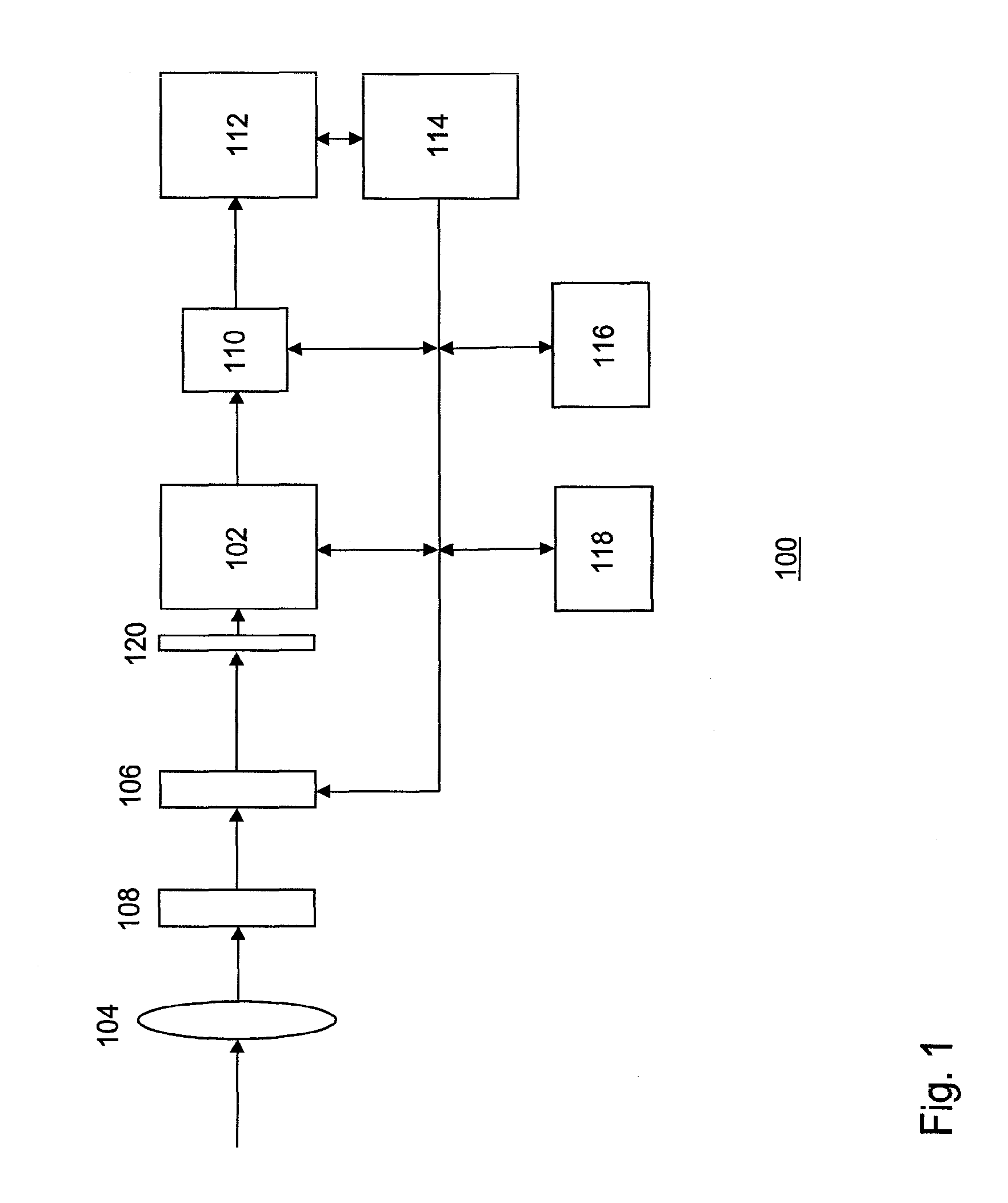
[0026]FIG. 1 illustrates an imaging system 100 according to one embodiment of the invention. The imaging system comprises an image sensor 102, a lens system 104 for focusing objects in a scene onto the imaging plane of the image sensor, a shutter 106 and an aperture system 108 with two or more apertures for allowing radiation into the imaging system. The imaging system may be part of a digital camera or integrated in a mobile phone, a webcam and other multimedia devices requiring image capturing functionality.

[0027]The shutter may be a mechanical shutter or, alternatively, the shutter may be an electronic shutter integrated in the image sensor. The image sensor comprises rows and columns of photosensitive sites (pixels) forming a two dimensional pixel array. The image sensor may be an CMOS (Complimentary Metal Oxide Semiconductor) active pixel sensor or an CCD (Charge Coupled Device) image sensor.

[0028]When the radiation is projected by the lens system onto the image sensor, each pi...


PUM


Abstract

A method is described of capturing an image. The method comprising the steps of: exposing an image sensor to radiation from a first part of the electromagnetic spectrum using a first aperture and to radiation from a second part of the spectrum using a second aperture having a different size than the first aperture; and, forming an image on the basis of first image data generated by the radiation from the first part of the spectrum and second image data generated by radiation from the second part of the spectrum.

Description

CROSS-REFERENCE TO RELATED APPLICATIONS[0001]The present application is a continuation of and claims priority of U.S. patent application Ser. No. 13 / 144,499, filed Sep. 27, 2011 which is a national stage application under 35 USC Section 371 of International patent application Serial No. PCT / EP2009 / 050502, filed Jan. 16, 2009, published as WO 2010 / 081556 A1 on Jul. 22, 2010 the contents of both of which are hereby incorporated by reference in their entirety.FIELD OF THE INVENTION[0002]The invention relates to improving the depth of field in an imaging system, and, in particular, though not exclusively, to a method for capturing an image having an improved depth of field, and an imaging system using such method.BACKGROUND OF THE INVENTION[0003]A limitation that exists in all optical systems used in cameras today is the tradeoff between aperture and the depth of field (DOF). An aperture determines the amount of light that enters the camera and the DOF determines the range of distances ...

Claims


Application Information

Patent Timeline
Patent Type & Authority Applications(United States)
IPC IPC(8): H04N5/33H04N5/232H04N5/355H04N5/357
CPCH04N5/33H04N5/3577H04N5/35536H04N5/23212H04N1/409H04N25/131H04N25/135H04N25/58H04N25/617
Inventor WAJS, ANDREW, AUGUSTINE
Owner DUAL APERTURE INT
Learn More