Heat exchanger

a heat exchanger and plate technology, applied in the field of heat exchangers, can solve the problems of high stress in the relatively thin-walled plates of the plate stack, and achieve the effects of reducing the risk of boiling, and reducing the stress in the corner region

Active Publication Date: 2016-03-24
MAHLE INT GMBH
View PDF13 Cites 4 Cited by
  • Summary
  • Abstract
  • Description
  • Claims
  • Application Information

AI Technical Summary

Benefits of technology

[0019]Here, it is particularly expedient if the rounded widening is formed in the bottom such that the dimension, measured along the long side, of the edge region of relatively low height decreases in the direction of the middle of the fluid duct proceeding from the side wall. In this way, a continuous transition is realized, which reduces the stresses and at the same time keeps the risk of boiling relatively low.
[0020]Here, it is particularly advantageous if the dimension of the rounded widening decreases in arcuate fashion. This also reduces the stresses in the corner region of the fluid duct or of the plates.
[0021]It is particularly advantageous if the dimension of the rounded widening decreases in S-shaped fashion.
[0022]It is particularly advantageous if the rounded widening also extends into at least one side wall, preferably into both side walls. In this way, the transition from the bottom to the side wall in the region of the corner is improved with regard to the occurring stresses, and the stresses in the material of the plate are reduced.
[0023]It is also advantageous if the rounded widening is formed in a side wall such that the dimension of the edge region of relatively low height in the longitudinal direction of the flow duct decreases in the direction of the middle of the height of the side wall proceeding from the bottom. In this way, the clear inner width of the fluid duct at the side wall is reduced by the rounded region only over a part of the height.
[0024]It is also expedient if the dimension of the rounded widening decreases in arcuate fashion. It is thus also advantageous if the dimension of the rounded widening decreases in S-shaped fashion.

Problems solved by technology

The temperature transition from the very hot, non-cooled gas inlet region of the second flow duct to that region of the heat exchanger which is connected to the coolant leads to high stresses owing to the different thermal expansion owing to the different temperatures.
Owing to the different prevailing temperatures, the diffuser and the plates expand to different extents, resulting in high stresses in the relatively thin-walled plates of the plate stack, in particular in the corners of the plates at the hot-gas inlet.
Nevertheless, further measures may be necessary for reducing the thermal stresses in the plate corners, because these are particularly susceptible to thermally induced stresses.

Method used


Image

  • Heat exchanger
  • Heat exchanger
  • Heat exchanger

Examples


Embodiment Construction

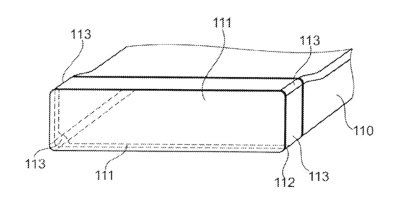
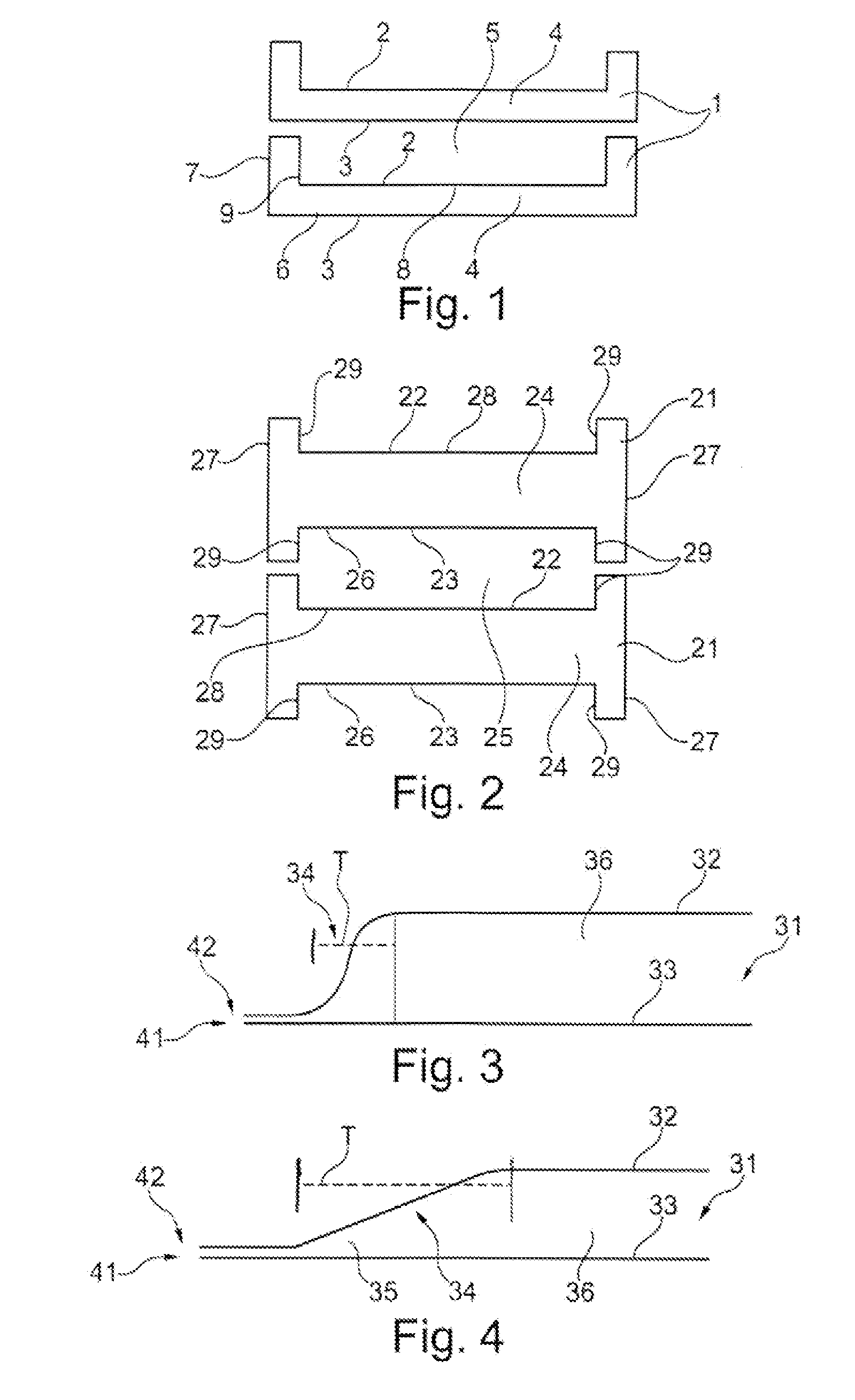
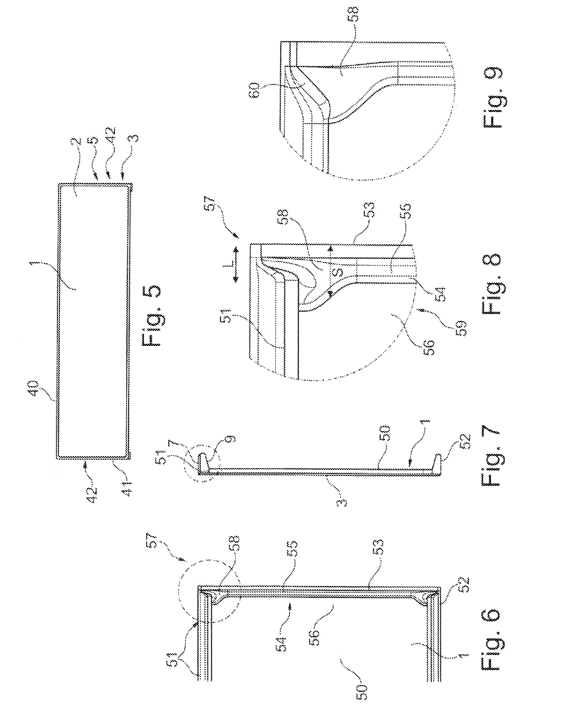
[0038]FIG. 1 shows a schematic arrangement of two plate pairs 1 which are each formed from a first plate 2 and a second plate 3 and which form a first fluid duct 4 for a first fluid between the plates 2, 3, wherein a second fluid duct 5 for a second fluid is formed between respectively adjacent plate pairs 1. Here, the plates 2, 3 preferably have a substantially planar bottom 6, 8, and side walls 7, 9 which project from said bottom. The respective plates 2, 3 of a plate pair 1 are placed one on top of the other and are connected to one another in fluid-tight fashion, for example by brazing, at their edge in order to form the sealed fluid duct. Either on one of the side walls 7, 9 or on both side walls 7, 9 and / or on the bottom 6, 8, there are provided openings (not illustrated) for the admission of the first fluid into the first fluid duct 4 or for the discharge of said first fluid out of the first fluid duct 4 again. The second fluid ducts 5 are normally designed to be open at thei...


PUM


Abstract

The invention relates to a heat exchanger, in particular exhaust-gas cooler, having tubes of unipartite form or formed from two shell-like plates, which tubes form a first and a second fluid duct, wherein the respective fluid ducts are arranged adjacent to one another, wherein the first fluid duct is designed to be open at at least one of its ends for the inflow and/or outflow of the first fluid, wherein, at the ends, the tubes are, by way of an inward or outward step, designed such that the second fluid ducts are closed at the end side, wherein the step has a greater extent T in the tube longitudinal direction in the corner regions of the tube than between the corner regions.

Description

TECHNICAL FIELD[0001]The invention relates to a heat exchanger, in particular a charge-air cooler or an exhaust-gas cooler for a motor vehicle, as per the preamble of claim 1.PRIOR ART[0002]Exhaust-gas coolers have the task of cooling hot exhaust gas of internal combustion engines in order that said cooled exhaust gas can be admixed to the intake air again. In this case, to increase the thermodynamic efficiency of an internal combustion engine, cooling to a very low level is sought. This principle is generally known as cooled exhaust-gas recirculation, and is used to achieve a reduction of pollutants, such as in particular nitrogen oxides, in the exhaust gas.[0003]DE 100 24 389 A1, DE 10 2005 034 137 A1 and WO 2014 / 040797 A1 have disclosed such heat exchangers, which are formed from a stack of plate pairs, wherein a first flow duct is formed between a pair of plates, and a second flow duct is formed between two plate pairs stacked one on top of the other.[0004]In this case, the firs...

Claims


Application Information

Patent Timeline
Patent Type & Authority Applications(United States)
IPC IPC(8): F28D7/16
CPCF02M25/0737F28D7/1661F28F9/0221F28D7/1684F28D9/0031F28D9/0037F28F1/006F28F1/025F28F1/045F02M26/32
Inventor MAUCHER, ULRICHBARWIG, JURGENENSMINGER, STEFFENPANTOW, EBERHARDLANG, CLAUDIAPEIFER, TIMOSCHMID, MATTHIASSTEIMER, JURGEN
Owner MAHLE INT GMBH
Why Eureka
Try Eureka