
Fail safe ball joint

Inactive Publication Date: 2016-03-24
RANE
View PDF1 Cites 1 Cited by
  • Summary
  • Abstract
  • Description
  • Claims
  • Application Information

AI Technical Summary

Benefits of technology

The technical effect of this patent is to improve the force that separates the ball in a steering ball joint mechanism, which can make driving safer for vehicles. This is achieved by positioning a retainer seat between the ball pin and the bearing cup to improve the separation force between the two components.

Problems solved by technology

However, in reality there is a gradual degradation of performance and response until point of overhaul.
This undesirable consequence is primarily because of component wear contributed by elements of tribology, environmental conditions, service usage and quality of maintenance.
Cumulative effects of low quality inspection, maintenance and service of ball joints on a vehicle lead to the ball socket separation.
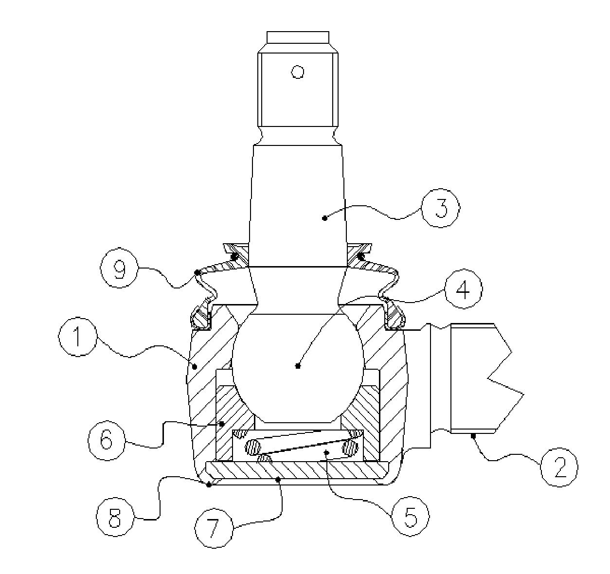
Accelerated corrosion of the ball pin [3] and the socket housing [1] contributed by failure of boot seal causes entry of water, mud and grit contaminating the grease which leads to metal to metal contact resulting in undesired frictional increase.
Subsequently, prolonged usage under such undefined conditions has a negative impact on significant dimensions namely reduction in the ball head diameter and expansion of the socket housing [1] back opening diameter which leads to excess free play in the ball joint and eventually resulting in ball socket separation.
However, construction requires additional critical parts for intended functionality and hence is complex.
However, construction cannot withstand pull-out forces in the range of 9 kN that are pre-requisite for vehicle steering linkage ball joints.
However, construction is complex due to more number of parts, reducing articulation angle which is essential and increasing product dimensions.

Method used


Image

  • Fail safe ball joint
  • Fail safe ball joint
  • Fail safe ball joint

Examples


Embodiment Construction

[0034]The present invention as discussed hereinbefore relates to a steering metallic ball joint mechanism which eliminates undesirable ball socket separation resulting in complete loss of vehicle control. Further, to improve the ball socket separation force in the steering ball joint mechanism subsequently improving vehicle safety.

[0035]Referring to FIG. 2, in one embodiment, the steering ball joint mechanism includes socket housing [1] with a stem [2]; at least one ball pin [3] with a spherical head [4] encapsulated in top metallic bearing cup [6] and the socket housing [1]; at least one end cap [7] with or without grease nipple provision; an elastic device [5] positioned between the top metallic bearing cup [6] and end cap [7], and a boot [9] mounted on the socket housing [1] encapsulating the ball pin [3] prevent entry of contaminants, characterized in that said ball pin [3] with spherical head [4] is provided with integral retainer seat [10]. The retainer seat [10] is integrated...


PUM


Abstract

The present invention relates to a steering metallic ball joint mechanism which eliminates undesirable ball socket separation resulting in complete loss of vehicle control. Further, the present invention aims to improve the ball socket separation force in the steering ball joint mechanism subsequently improving vehicle safety. In one aspect, the steering ball joint mechanism is provided with an integral retainer seat on a ball stud to improve ball socket separation force, said ball stud and integral retainer seat forms a single entity. In another aspect, the steering ball joint mechanism is provided with retainer seat positioned in between ball pin and top of bearing cup. The simple construction and application of the retainer seat on a ball joint mechanism aides to retain defined steering linkage configuration even when undesirable excess wear has occurred which can be identified by the user before ball socket separation occurs.

Description

FIELD OF INVENTION[0001]The present invention relates to an automotive steering ball joint mechanism. More specifically, the present invention relates to a steering metallic ball joint mechanism which eliminates undesirable ball socket separation resulting in complete loss of vehicle control. Further, the present invention aims to improve the ball socket separation force in the steering ball joint mechanism subsequently improving vehicle safety.DESCRIPTION OF PRIOR ART[0002]In an automobile, ball joints are used on virtually every automobile and work similar to the ball and socket design of the human hip joint. The steering mechanism in automobiles is provided with the ball joint linkage assemblies in other words commonly referred to as Drag Link Assembly (DLA) and Tie Rod Assembly (TRA). The DLA links the steering gear drop arm on one side and vehicle wheel-knuckle arm assembly on the other side. The TRA links front wheel (left side and right side) stub axles. Such an arrangement p...

Claims


Application Information

Patent Timeline
IPC IPC(8): F16C11/06
CPCF16C11/0671F16C11/0623F16C11/0604F16C2326/24F16C11/0628F16C11/0647F16C11/0652
Inventor SUNDARARAJAN, S.VIJAYANAND, A.VASANTH, K.ALEXANDER, BEN, GEORGE, K.
Owner RANE
Learn More