
Systems and methods for validating wind farm performance measurements

a technology of wind farm and measurement method, applied in the field of wind farm, can solve the problems of affecting the power output of the downwind turbine, affecting the performance of the wind farm, and affecting the impact of the neighboring turbin

Active Publication Date: 2016-03-24
GENERAL ELECTRIC CO
View PDF6 Cites 43 Cited by
  • Summary
  • Abstract
  • Description
  • Claims
  • Application Information

AI Technical Summary

Benefits of technology

The present invention provides a method and system for validating wind farm performance measurements after upgrades have been installed. The method involves measuring operating data from wind turbines and generating baseline models of performance from the data. An optimal baseline model is selected and compared to the actual performance of the wind farm after modifications. This allows for the identification of wind farm performance measurements that indicate errors. The technical effects of the invention include improved accuracy in measuring wind farm performance and the ability to quickly detect and address errors.

Problems solved by technology

Often, while maximizing the power output of a single wind turbine, neighboring turbines may be negatively impacted.
For example, downwind turbines may experience large wake effects caused by an upwind turbine.
Because of these wake effects, downwind turbines receive wind at a lower speed, drastically affecting their power output (as power output is proportional to wind speed).
Moreover, wind turbulence negatively affects the fatigue loads placed on the downwind turbines, and thereby affects their life (as life is proportional to fatigue loads).
Consequently, maximum efficiency of a few wind turbines may lead to sub-optimal power output, performance, or longevity of other wind turbines in the wind farm.
The nacelle anemometer approach, however, is sometimes hindered due to imprecision of nacelle anemometer measurements and the projection of these measurements into AEP estimates.
Further, such an approach may be less preferred than use of an external met mast in front of a wind turbine, but is in widespread use due to the generally prohibitive cost of the met mast approach.
In addition, even when nacelle anemometers are calibrated correctly, individual wind power curve methods are not able to discern the benefit of upgrades, such as wake minimization technologies, that can create more wind for the farm to use.
Such an approach, however, is subject to the availability of the control turbine and further inaccuracies due to reliance on a single, more distant sensor.
Thus, it is difficult to show the benefit of upgrades to individual turbines.

Method used


Image

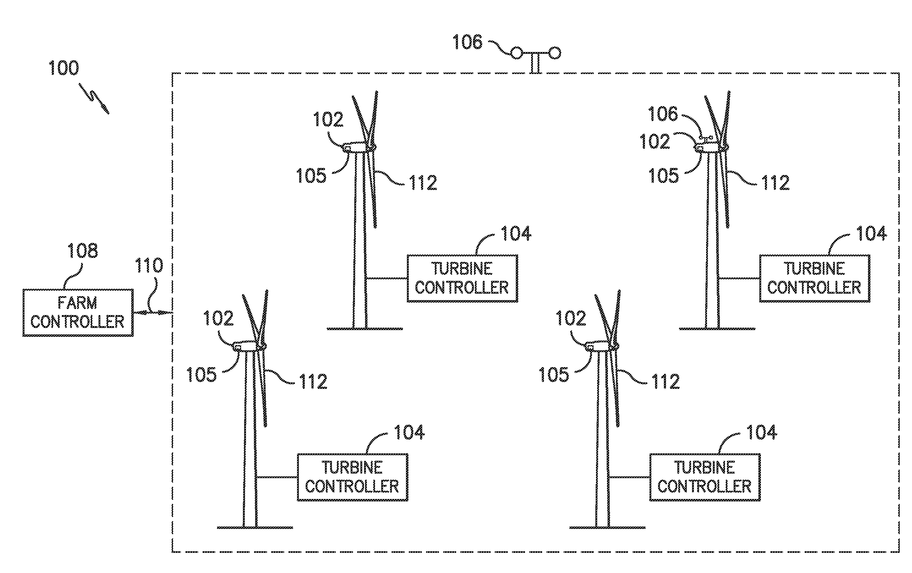
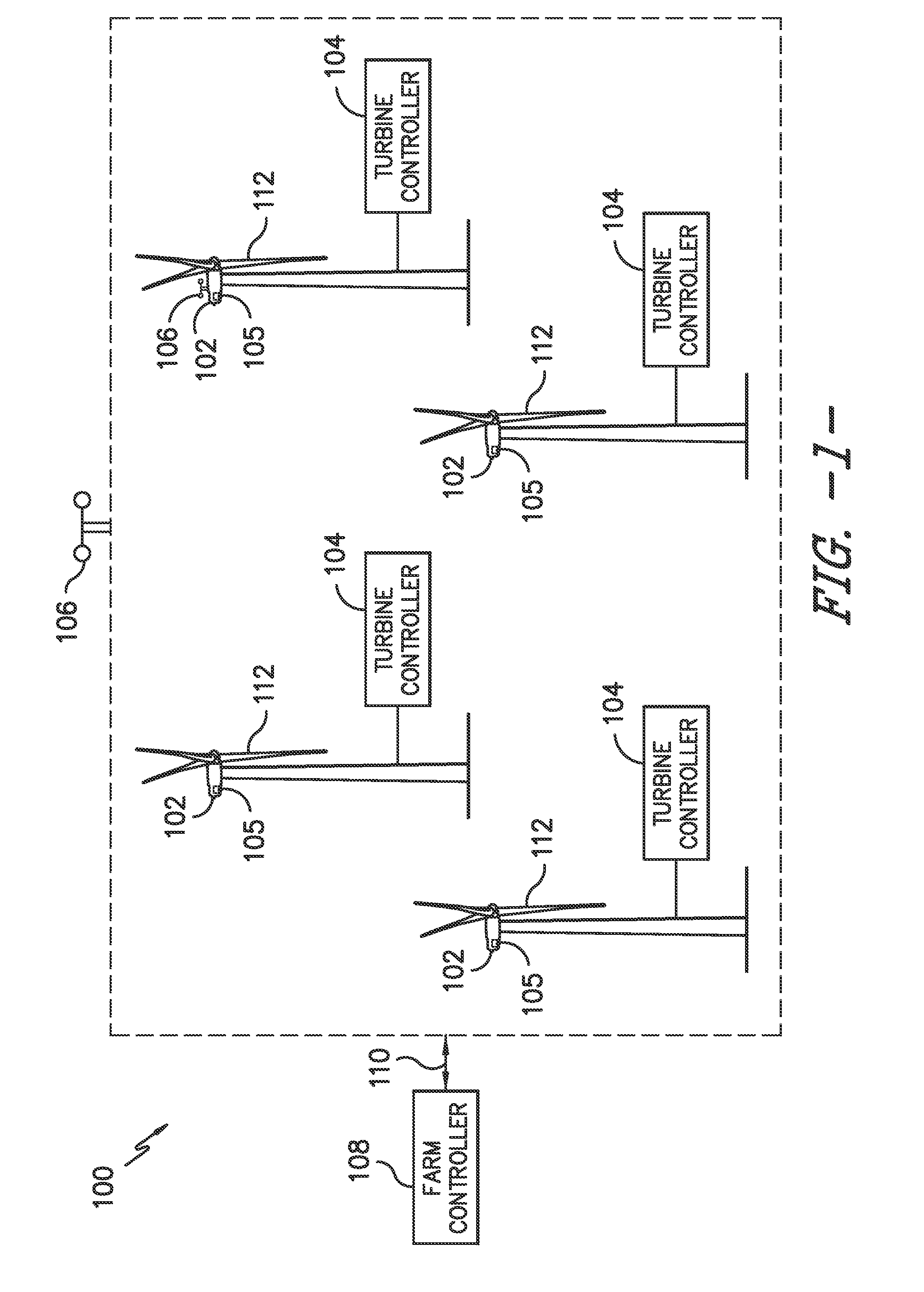
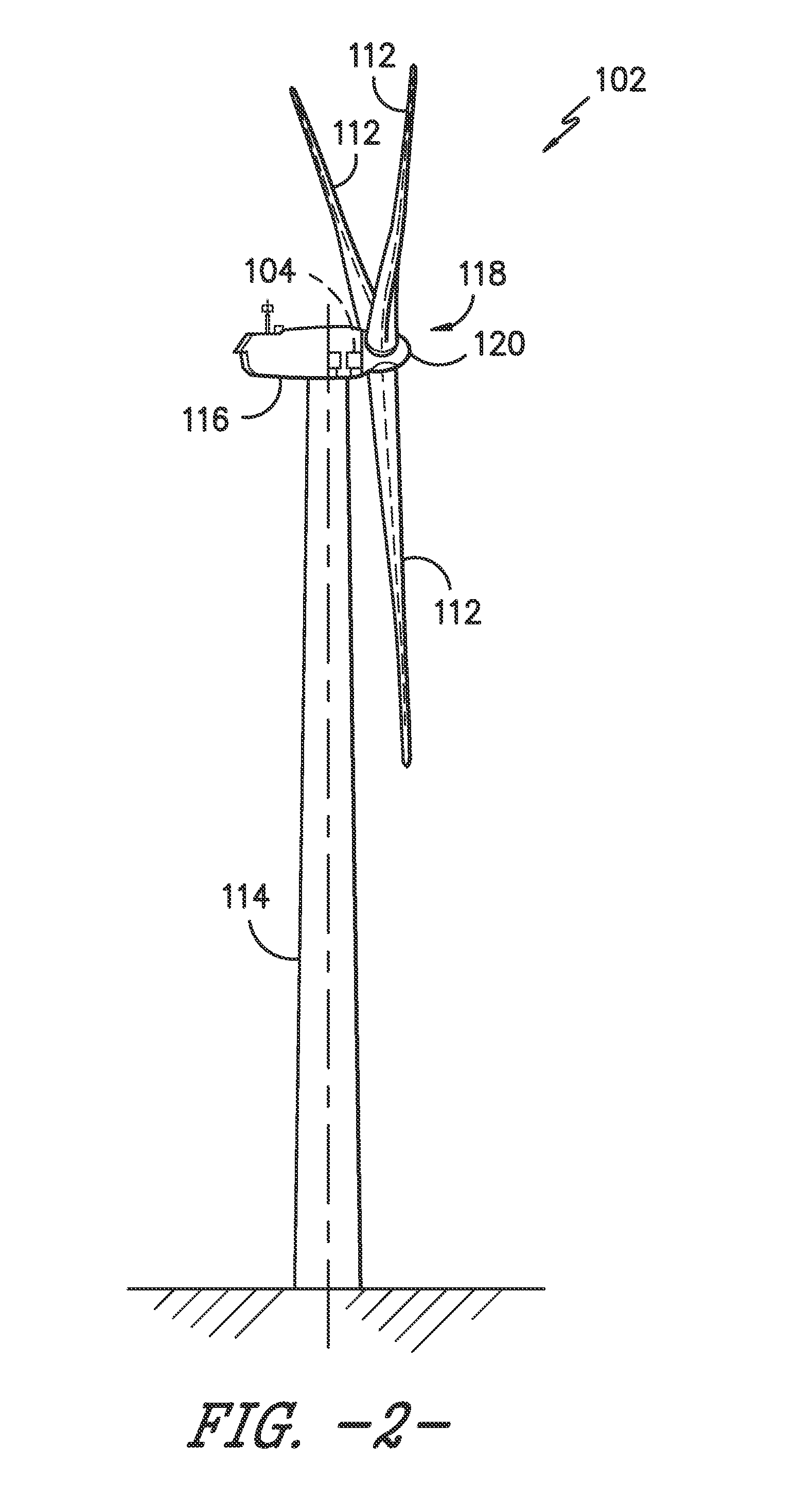
  • Systems and methods for validating wind farm performance measurements
  • Systems and methods for validating wind farm performance measurements
  • Systems and methods for validating wind farm performance measurements

Examples


Embodiment Construction

[0027]Reference now will be made in detail to embodiments of the invention, one or more examples of which are illustrated in the drawings. Each example is provided by way of explanation of the invention, not limitation of the invention. In fact, it will be apparent to those skilled in the art that various modifications and variations can be made in the present invention without departing from the scope or spirit of the invention. For instance, features illustrated or described as part of one embodiment can be used with another embodiment to yield a still further embodiment. Thus, it is intended that the present invention covers such modifications and variations as come within the scope of the appended claims and their equivalents.

[0028]Generally, the present disclosure is directed to improved systems and methods for validating or identifying wind farm performance measurements in a wind farm. For example, in one embodiment, the system is configured to validate wind farm performance m...


PUM


Abstract

The present disclosure is directed to systems and methods for validating and / or identifying wind farm performance measurements so as to optimize wind farm performance. The method includes measuring operating data from one or more wind turbines of the farm. Another step includes generating a plurality of baseline models of performance of the wind farm from at least a portion of the operating data. Thus, each of the baseline models of performance is developed from a different portion of operating data so as to provide comparable models. The method also includes selecting an optimal baseline model and comparing the optimal baseline model with actual performance of the wind farm. In a particular embodiment, the actual performance of the wind farm is determined after one or more wind turbines of the wind farm is modified by one or more upgrades.

Description

FIELD OF THE INVENTION[0001]The present disclosure relates generally to wind farms and, more particularly, to systems and methods for validating wind farm performance improvement measurements, e.g. power output.BACKGROUND OF THE INVENTION[0002]Wind power is considered one of the cleanest, most environmentally friendly energy sources presently available, and wind turbines have gained increased attention in this regard. A modern wind turbine typically includes a tower, generator, gearbox, nacelle, and one or more rotor blades. The rotor blades capture kinetic energy of wind using known airfoil principles. For example, rotor blades typically have the cross-sectional profile of an airfoil such that, during operation, air flows over the blade producing a pressure difference between the sides. Consequently, a lift force, which is directed from a pressure side towards a suction side, acts on the blade. The lift force generates torque on the main rotor shaft, which is geared to a generator ...

Claims


Application Information

Patent Timeline
Patent Type & Authority Applications(United States)
IPC IPC(8): F03D7/00F03D9/00
CPCF03D11/0091F03D9/005F03D7/00F03D7/048H02J3/00F05D2270/335F05B2260/84F05D2270/20F03D9/257F03D17/00H02J2203/20H02J2300/40H02J2300/28H02J3/381Y02E10/76Y02E10/72Y02E60/00Y04S40/20F05B2270/204
Inventor EVANS, SCOTT, CHARLESZHANG, ZHANPANGREGG, PETER, ALANIYENGAR, SATISH, G.
Owner GENERAL ELECTRIC CO
Learn More