Method of Stratigraphic Modeling of Faults

Active Publication Date: 2016-03-17
CHEVROU USA INC
View PDF6 Cites 1 Cited by
  • Summary
  • Abstract
  • Description
  • Claims
  • Application Information

AI Technical Summary

Benefits of technology

This patent is about a new method for creating grids for forward stratigraphic modeling, which allows for the representation of faults and the ability to segment and move the grid. The method is efficient and easy to repeat, and can access previous deposits stored in the grid. The technical effects of this patented method include improved access to individual cells in the grid, segmentation and movement of the grid, and efficient structural modeling with minimal changes to the overall topology of the grid.

Problems solved by technology

One of the significant technology hurdles in develop realistic forward stratigraphic models in the environment where there are syndepositional structure movement are the abilities for the model to represent the lateral move of the structure blocks.
Not capturing these lateral displacement of deposits will likely result in unrealistic stacking patterns, erroneous rock property distributions and subsequently significant reduce the applicability of the stratigraphy models and their predictive capabilities.
The primary challenge in representing lateral movement of structure blocks in a stratigraphic model is the need for current existing gridding algorithms that can efficiently performs two essential tasks simultaneously: (1) allow the forward stratigraphy model to access the previously deposited sediments in the computational grid efficiently at any location in the computational domain, and at any time during the simulation, for modeling sediment erosion and deposition processes; and (2) allow lateral and vertical movement of any part of the grid to realistically represent the structure move.
While a 3D unstructured grid can be re-meshed to represent the structure move realistically, the algorithm is computational expensive and not efficient.
More importantly, 3D fully unstructured mesh may not be optimal for forward stratigraphic model, as such a mesh generally needs a significant amount of computations for stratigraphic models to access the sedimentary information stored in the mesh.
However, the grid does not offer any possibilities for perform lateral translations of any part of the grid without having to resort to a complete re-gridding, which will be computational prohibitive if the operation has to be performed frequently.

Method used


Image

  • Method of Stratigraphic Modeling of Faults
  • Method of Stratigraphic Modeling of Faults
  • Method of Stratigraphic Modeling of Faults

Examples


Embodiment Construction

[0030]Referring now to the Figures, embodiments of the disclosed methods will be described. As a threshold matter, embodiments of the methods may be implemented in numerous ways, as will be described in more detail below, including for example as a system (including a computer processing system), a method (including a computer implemented method), an apparatus, a computer readable medium, a computer program product, a graphical user interface, a web portal, or a data structure tangibly fixed in a computer readable memory. Several embodiments of the disclosed methods are discussed below. The appended drawings illustrate only typical embodiments of the disclosed methods and therefore are not to be considered limiting of its scope and breadth.

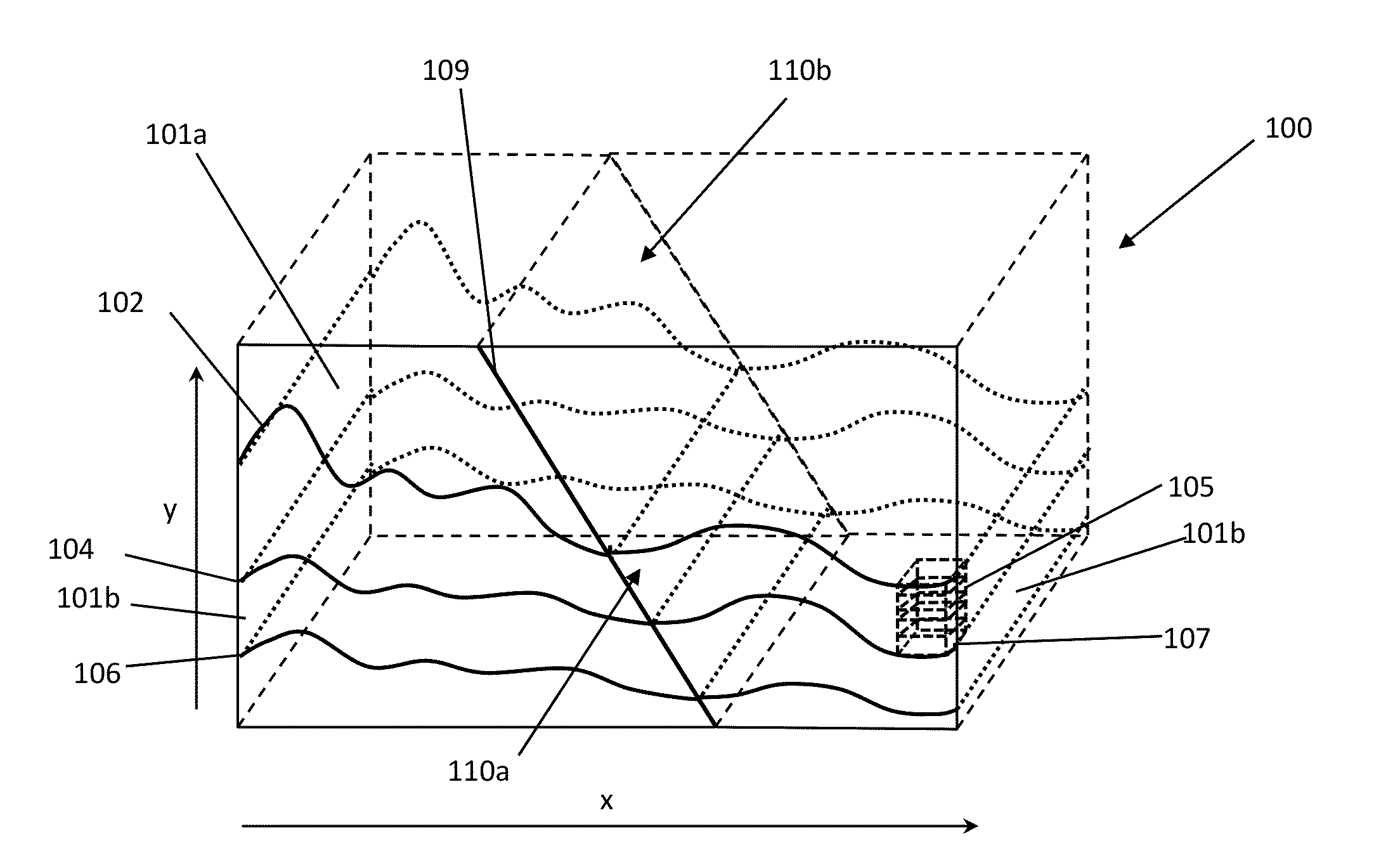
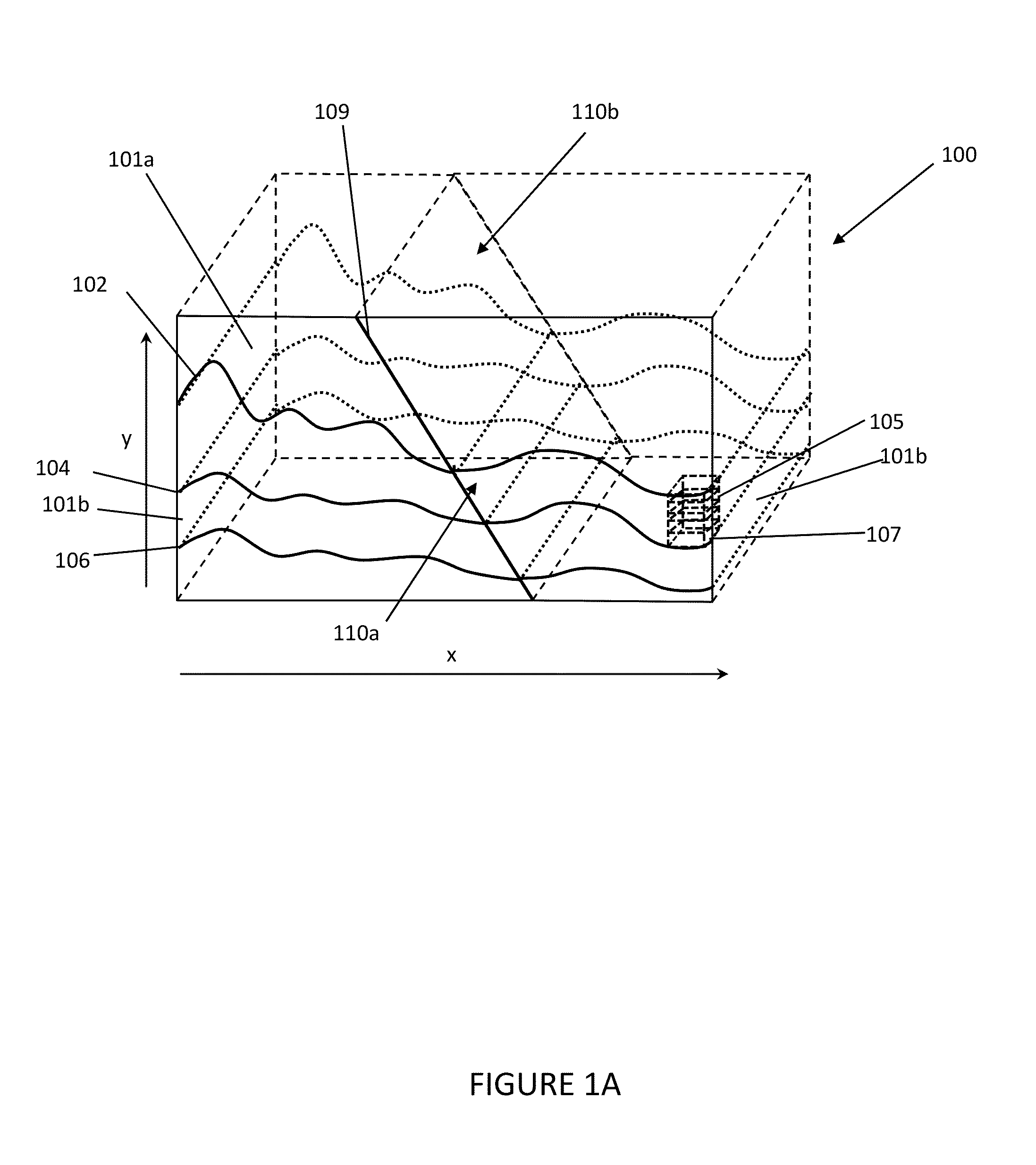
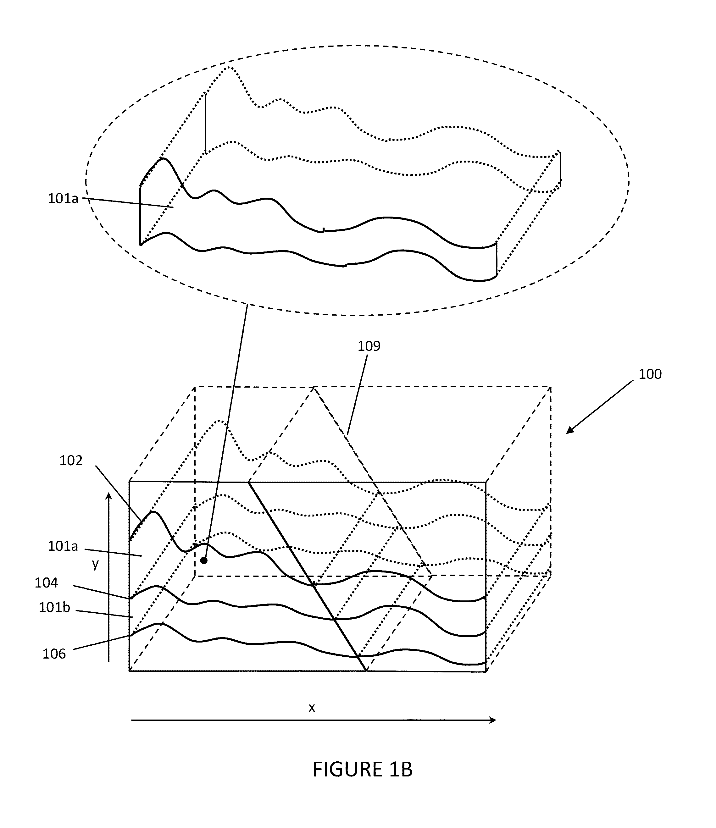
[0031]In an embodiment, the method involves, unlike a conventional grid where the absolute spatial position (x, y, z) of each cell is explicitly defined, the global structure of the grid may be represented using a parameterized scheme. Under this ...


PUM


Abstract

A new gridding method is disclosed for forward stratigraphic modeling that allows for syndepositional and / or postdepositional fault movement. The new gridding algorithm may represent both the lateral move of structure block, and provide efficiency that is comparable to the structured grid for forward stratigraphy model accessing previous deposited sediments stored in the grid. Embodiments of the disclosed methods allow for structural moves by performing a set of simple operations on the grid. The operations are generally simple, and do not change the overall topology of the grid. Therefore the operation can be easily repeated and the overall topological structure of the grid remains largely unchanged for simple access by the forward stratigraphic model. Further details and advantages of various embodiments of the method are described in more herein.

Description

CROSS-REFERENCE TO RELATED APPLICATIONS[0001]Not applicable.STATEMENT REGARDING FEDERALLY SPONSORED RESEARCH OR DEVELOPMENT[0002]Not applicableBACKGROUND[0003]1. Field of the Invention[0004]This invention relates generally to the field of geological exploration for hydrocarbons. More specifically, the invention relates to a method of stratigraphic modeling of faults.[0005]2. Background of the Invention[0006]One of the significant technology hurdles in develop realistic forward stratigraphic models in the environment where there are syndepositional structure movement are the abilities for the model to represent the lateral move of the structure blocks. One typical example is the growth fault, where the previously deposited sediments above the fault (hanging wall) not only moves downwards, but also moves away along the fault from the source of the sediments. Not capturing these lateral displacement of deposits will likely result in unrealistic stacking patterns, erroneous rock propert...

Claims


Application Information

Patent Timeline
IPC IPC(8): G01V99/00
CPCG01V99/005G01V2210/642G01V20/00G06F30/20
Inventor SUN, TAOPERLMUTTER, MARTINPYRCZ, MICHAEL JAMESSULLIVAN, MORGANHARRIS, ASHLEY
Owner CHEVROU USA INC
Why Eureka
Try Eureka