
Battery state detection device

a state detection and battery technology, applied in secondary battery servicing/maintenance, instruments, electrochemical generators, etc., can solve the problems of deterioration of such a secondary battery, gradual decrease of storable capacity (a current capacity, power capacity, etc., to effectively suppress the increase in manufacturing cost and device size, detect the state of the secondary battery in a shorter time, and effectively suppress the effect of increasing manufacturing cos

Inactive Publication Date: 2016-03-10
YAZAKI CORP
View PDF0 Cites 8 Cited by
  • Summary
  • Abstract
  • Description
  • Claims
  • Application Information

AI Technical Summary

Benefits of technology

This patent describes a method for charging a battery by measuring the voltage and current that is applied to it during the charging process. This measurement is made while the battery is being charged, without the need for a discharge unit or the entire charging process to be measured. The amount of power that is integrated into the battery during this period of charging is measured, and this information is used to detect the state of the battery. This method helps to reduce manufacturing costs and device size, and can provide a quicker way to detect the battery's state.

Problems solved by technology

It is known that deterioration of such a secondary battery progresses due to repetition of charging and discharging and that a storable capacity (a current capacity, a power capacity, or the like) gradually decreases.

Method used


Image

  • Battery state detection device
  • Battery state detection device
  • Battery state detection device

Examples


first embodiment

[0023]Hereinafter, a battery state detection device according to a first embodiment of the present invention will e described with reference to FIGS. 1, 2.

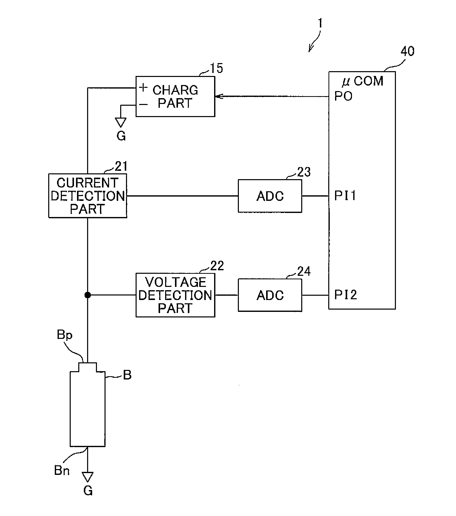
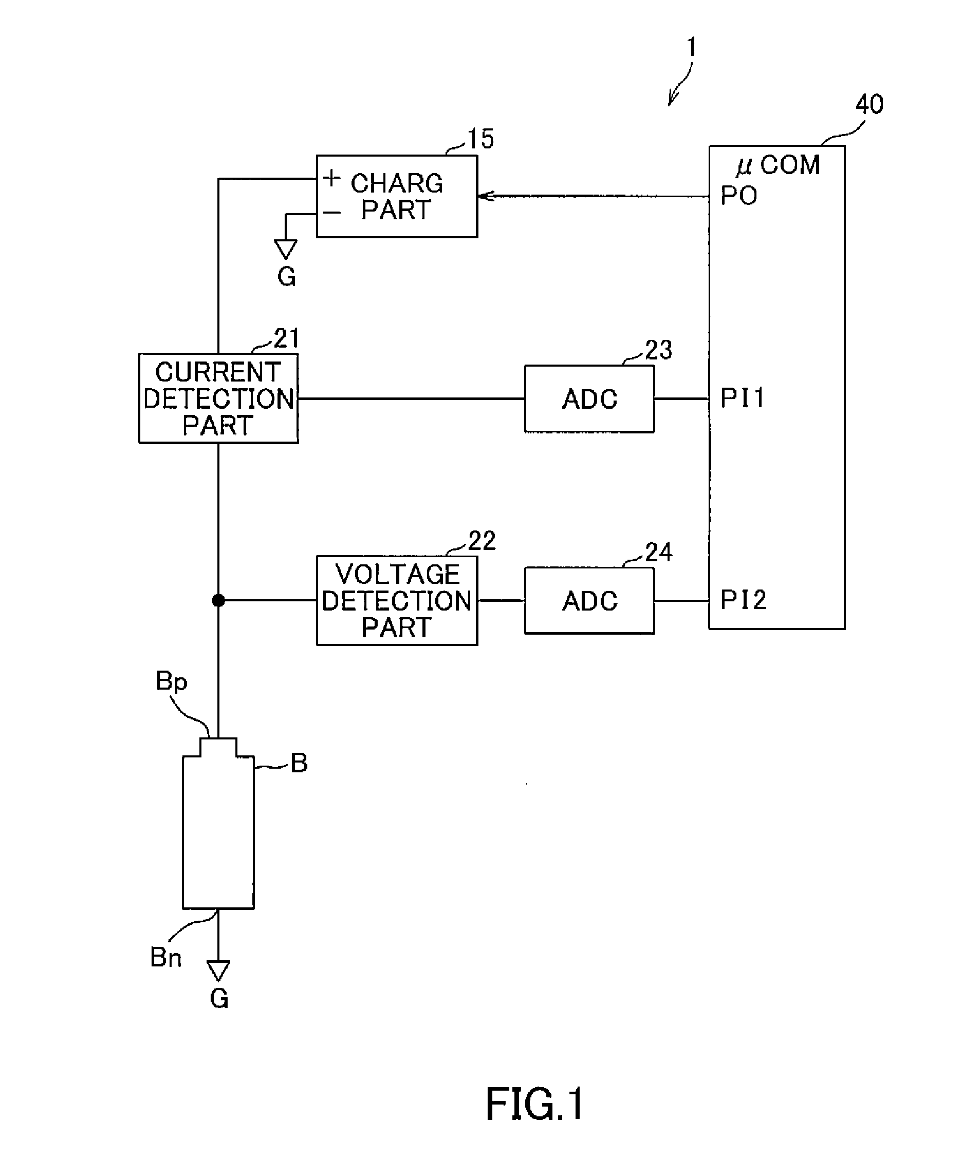
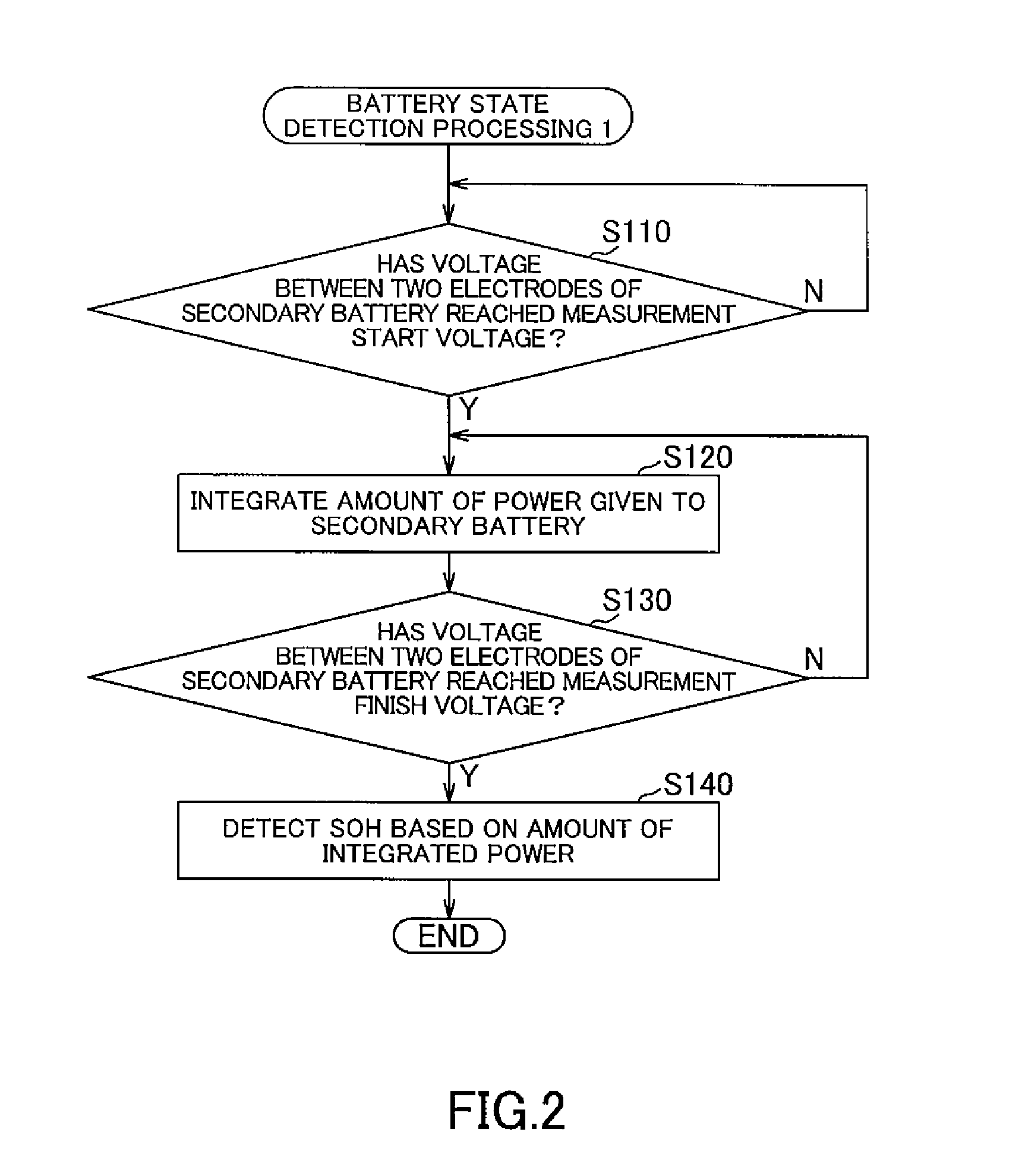
[0024]FIG. 1 is a diagram that illustrates a schematic configuration of the battery state detection device according to the first embodiment of the present invention. FIG. 2 is a flowchart that illustrates an example of battery state detection processing 1 (power integration) executed by a CPU of a microcomputer included in the battery state detection device in FIG. 1.

[0025]The battery state detection device of the present embodiment is, for example, mounted on an electric vehicle, connected between electrodes of a secondary battery included in the electric vehicle, and detects an SOH of the secondary battery as a state of the secondary battery. Needless to say, the battery state detection device may be applied to a device, a system, or the like including a secondary battery other than the electric vehicle.

[0026]As illustrated in ...

second embodiment

[0044]Hereinafter, a battery state detection device according to a second embodiment of the present invention will be described with reference to FIG. 3.

[0045]Instead of measuring the amount of integrated power Ps given to the secondary battery B in a part of the period from the time of complete discharge to the time of full charge in the aforementioned first embodiment, the battery state detection device of the present embodiment measures an amount of integrated current Is and detects an SOH of a secondary battery B based on the amount of integrated current Is. Specifically, a device configuration of the present embodiment is the same as the aforementioned battery state detection device 1, and instead of the battery state detection processing 1 illustrated in FIG. 2, a CPU of a μCOM 40 executes battery state detection processing 2 illustrated in FIG. 3. Accordingly, in the present embodiment, description of the device configuration is omitted, and only the battery state detection p...


PUM

PropertyMeasurementUnit
voltageaaaaaaaaaa
voltageaaaaaaaaaa
voltageaaaaaaaaaa

Abstract

In a battery state detection device, a μCOM detects that, during charge by a charge part, a voltage between both electrodes of a secondary battery has reached a predetermined measurement start voltage set higher than a voltage between the both electrodes of the secondary battery at the time of complete discharge, and detects that, during the charge by the charge part, the voltage between the both electrodes of the secondary battery has reached a predetermined measurement finish voltage set higher than the measurement start voltage. Then, the μCOM measures an amount of integrated power given to the secondary battery in a period from the detection of the measurement start voltage to the detection of the measurement finish voltage, and detects an SOH of the secondary battery based on the amount of integrated power measured by integrated power amount measurement unit.

Description

TECHNICAL FIELD[0001]The present invention relates to a battery state detection device for detecting a state of a secondary battery.BACKGROUND ART[0002]For example, as a power source of an electric motor, a secondary battery, such as a lithium ion rechargeable battery or a nickel-metal hydride rechargeable battery, is mounted on various kinds of vehicles, such as an electric vehicle (EV) travelled using the electric motor and a hybrid vehicle (HEV) travelled using both an engine and the electric motor.[0003]It is known that deterioration of such a secondary battery progresses due to repetition of charging and discharging and that a storable capacity (a current capacity, a power capacity, or the like) gradually decreases. Moreover, in the electric vehicle or the like using the secondary battery, the storable capacity is obtained by detecting a degree of deterioration as a state of the secondary battery, and a travelable distance of the vehicle with the secondary battery, a life of th...

Claims


Application Information

Patent Timeline
Patent Type & Authority Applications(United States)
IPC IPC(8): H01M10/48G01R31/36
CPCG01R31/3679G01R31/3648H01M10/48H01M10/44H01M2010/4271G01R31/3828G01R31/3835Y02E60/10G01R31/392
Inventor TAKAHASHI, NOBUYUKISYOUDA, TAKAHIRO
Owner YAZAKI CORP
Learn More