
Magnetic current sensor and current measurement method

a current measurement and current sensor technology, applied in the direction of voltage/current isolation, base element modification, instruments, etc., can solve the problems of poor reproducibility, difficult electric insulation, and limitations of each of these sensors, and achieve excellent linearity between a current and an output voltage, suppressed magnetic hysteresis, and increased current

Active Publication Date: 2016-03-03
MURATA MFG CO LTD
View PDF5 Cites 9 Cited by
  • Summary
  • Abstract
  • Description
  • Claims
  • Application Information

AI Technical Summary

Benefits of technology

The present invention is a magnetic current sensor and current measurement method that aims to reduce magnetic hysteresis and improve linearity between current and output voltage near 0 mA. It also ensures excellent insulation between the current circuit side and MR device side, resulting in increased current, reduced size, and cost.

Problems solved by technology

Each of these sensors has limitations.
In particular, the current sensor of (1) has a problem in that electric insulation is not easy.
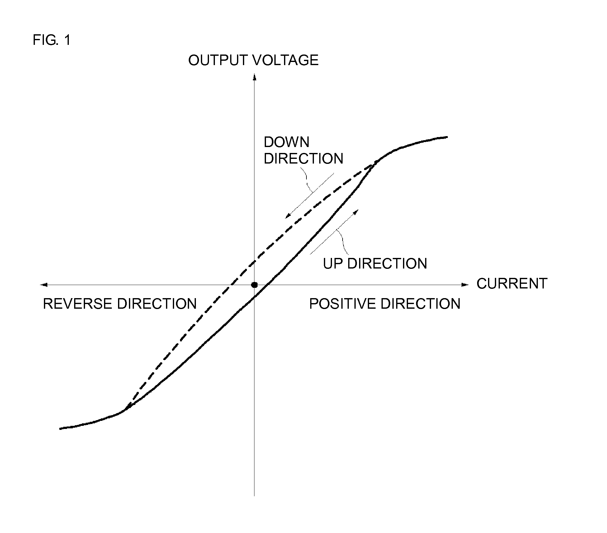
With regard to the current sensor of (3), reproducibility is poor since there exists magnetic hysteresis and the size of the current sensor needs to be increased since the sensitivity of a Hall element is lower than that of an MR device.
Finally, with regard to the current sensor of (4), reproducibility is poor since a barber-pole MR device is used and, hence, there exists magnetic hysteresis.

Method used


Image

  • Magnetic current sensor and current measurement method
  • Magnetic current sensor and current measurement method
  • Magnetic current sensor and current measurement method

Examples


example

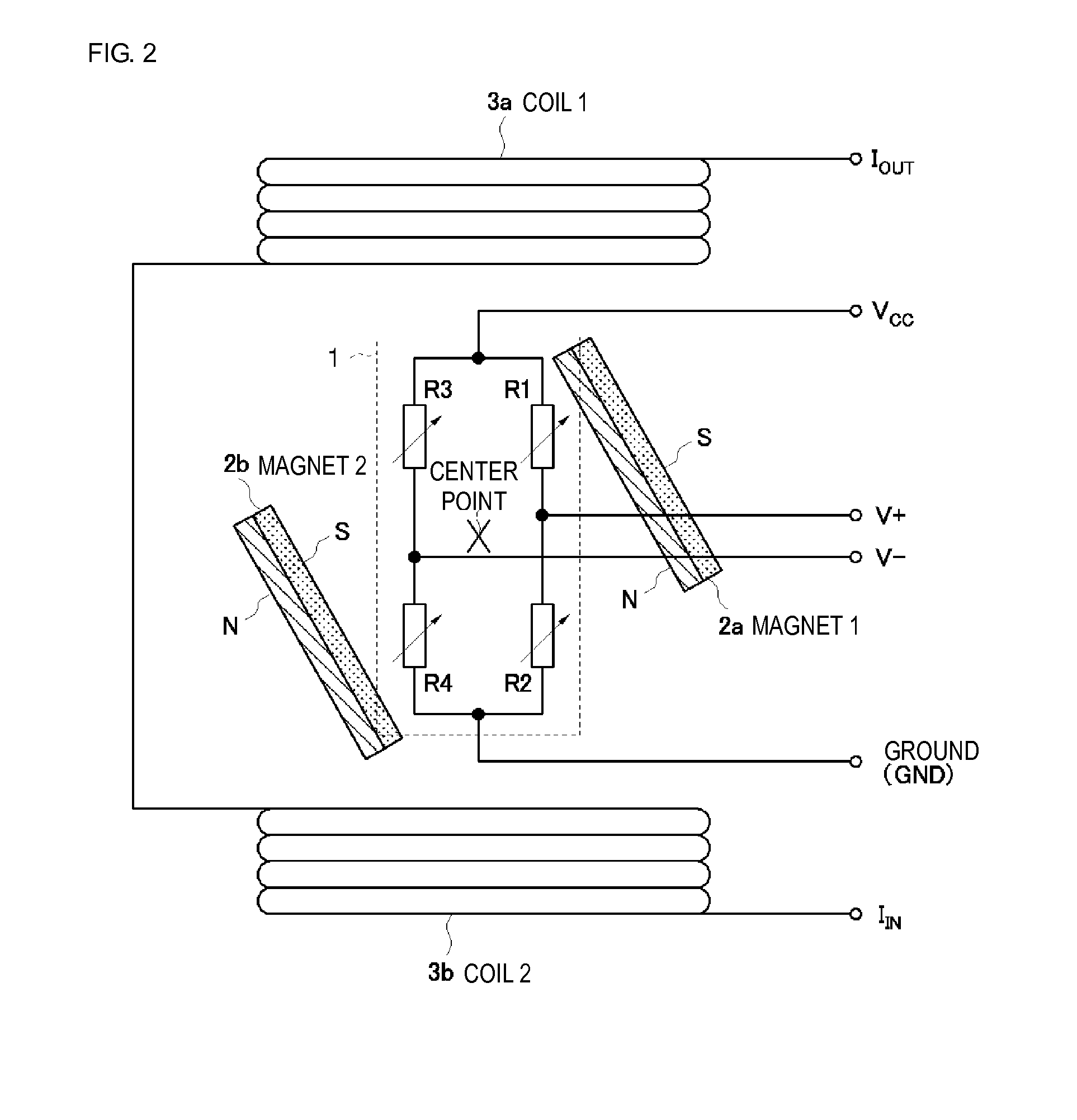
[0038]A magnetic current sensor and a current measurement method according to an example of the present invention will be described with reference to FIG. 6, FIG. 7, and FIG. 8. MR devices R1-R4 forming a bridge circuit 1 are made of a thin film which is an alloy (permalloy) of iron (Fe)-nickel (Ni). The thickness of the permalloy thin film is 400 nm. Each of the MR devices has a zigzag shape, and is composed of patterns each having a long-side length of 230 μm and a width of 9 μm. Twenty-one of these patterns are connected to each other so as to form a zigzag shape. The interval between neighboring patterns is 2 μm.

[0039]Each of the magnet 1 (2a) and the magnet 2 (2b) forming a pair of permanent magnets has the following dimensions: the length (width of a magnet surface that faces another magnet) is 1.1 mm; the height (depth of a magnet surface that faces another magnet) is 0.6 mm; and the thickness is 0.2 mm. The material of the permanent magnet is samarium cobalt (SmCo). An angle...

embodiment 1

Alternative Embodiment 1

[0045]A magnetic current sensor including: a Wheatstone bridge circuit formed of four magnetoresistance devices; bias magnetic field application means for applying a bias magnetic field to the magnetoresistance devices; and air-core coils provided on both sides of the Wheatstone bridge circuit, where the Wheatstone bridge circuit generates a voltage corresponding to an induction magnetic field generated by a current to be measured flowing through the air-core coils.

embodiment 2

Alternative Embodiment 2

[0046]The magnetic current sensor according to Supplemental description 1, where maximum-magnetic-sensitivity axes of the magnetoresistance devices neighboring each other in the Wheatstone bridge circuit are orthogonal to each other.


PUM


Abstract

A magnetic current sensor including a Wheatstone bridge circuit formed of four magnetoresistance devices; bias magnetic field application that applies a bias magnetic field to the magnetoresistance devices; and air-core coils provided on both sides of the Wheatstone bridge circuit. The Wheatstone bridge circuit generates a voltage corresponding to an induction magnetic field generated by a current to be measured flowing through the air-core coils. According to the magnetic current sensor and current measurement method, the linearity between a current and an output voltage is near 0 mA as a result of magnetic hysteresis being suppressed, and an increase in current and a reduction in size and cost are realized as a result of insulation between the current circuit side and the MR device side being excellent.

Description

CROSS-REFERENCE TO RELATED APPLICATION[0001]The present application is a continuation of PCT / JP2013 / 003007 filed May 10, 2013, the entire contents of which are incorporated herein by reference.FIELD OF THE INVENTION[0002]The present invention relates to a magnetic current sensor and a current measurement method for detecting a current flowing through an electronic circuit or the like by using a magnetoresistance effect.BACKGROUND OF THE INVENTION[0003]In recent years, in accordance with, for example, the widespread use of electric cars or the introduction of smart meters and power visualization systems, the market for current sensors for these purposes is rapidly increasing. The major four types of current sensor used by the market include (1) a shunt resistance method, (2) a current transformer method, (3) a Hall effect magnetic current sensor, and (4) a magnetic current sensor based on a magnetoresistance (MR) method.[0004]Each of these sensors has limitations. In particular, the ...

Claims


Application Information

Patent Timeline
Patent Type & Authority Applications(United States)
IPC IPC(8): G01R15/20G01R19/00
CPCG01R15/205G01R19/0092G01R33/123G01R33/093
Inventor ZHANG, ZHENHONG
Owner MURATA MFG CO LTD
Learn More