
Diffractive Waveplate Lenses for Correcting Aberrations and Polarization-Independent Functionality

a technology of diffractive waveplate and lens, applied in the field of optical lenses, can solve the problems of affecting increasing the weight of such lenses, and increasing the size of the lens, and reducing the quality of the lens with increasing siz

Active Publication Date: 2016-02-18
U S ARMY NATICK SOLDIER RES DEV & ENG CENT +2
View PDF7 Cites 32 Cited by
  • Summary
  • Abstract
  • Description
  • Claims
  • Application Information

AI Technical Summary

Benefits of technology

[0006]The objective of the present invention is providing a thin film structure that provides the ability to correct aberrations including, but not limited to, spherical aberration.
[0008]The third objective of the present invention is providing an imaging system consisting of one or more thin film lenses with spherically or cylindrically symmetric continuous structure, in combination with a birefringent lens, thus allowing electromagnetic radiation of any polarization to be focused to the same point in space, for a spherically symmetric structure; or to the same line segment in space, for a cylindrically symmetric structure.
[0010]The fifth objective of the present invention is providing a combination of lenses with spherically or cylindrically symmetric continuous thin film structure that has the capability to correct the chromatic aberrations of a conventional imaging system employing one or more refractive lenses.
[0011]The sixth objective of the present invention is providing a combination of lenses with spherically or cylindrically symmetric continuous thin film structure that has the capability to simultaneous correct both the spherical and chromatic aberrations of a conventional imaging system employing one or more refractive lenses.

Problems solved by technology

The weight of such lenses increases strongly with diameter making them expensive and prohibitively heavy for applications requiring large area.
Also the quality of a lens typically decreases with increasing size.
The need to grind and polish conventional lenses with non-spherical surfaces can make such lenses extremely expensive.
Segmented lenses such as Fresnel lenses are relatively thin, however, the structural discontinuities result in severe aberrations.
Uses of holographic lenses are limited by the compromise of efficiency, spectral bandwidth and dispersion.

Method used


Image

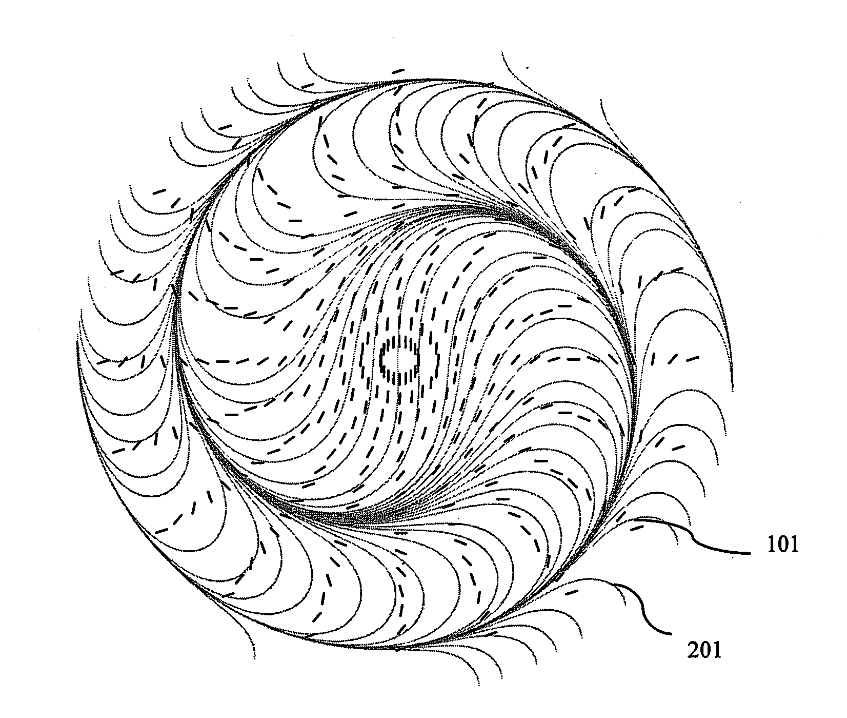
  • Diffractive Waveplate Lenses for Correcting Aberrations and Polarization-Independent Functionality
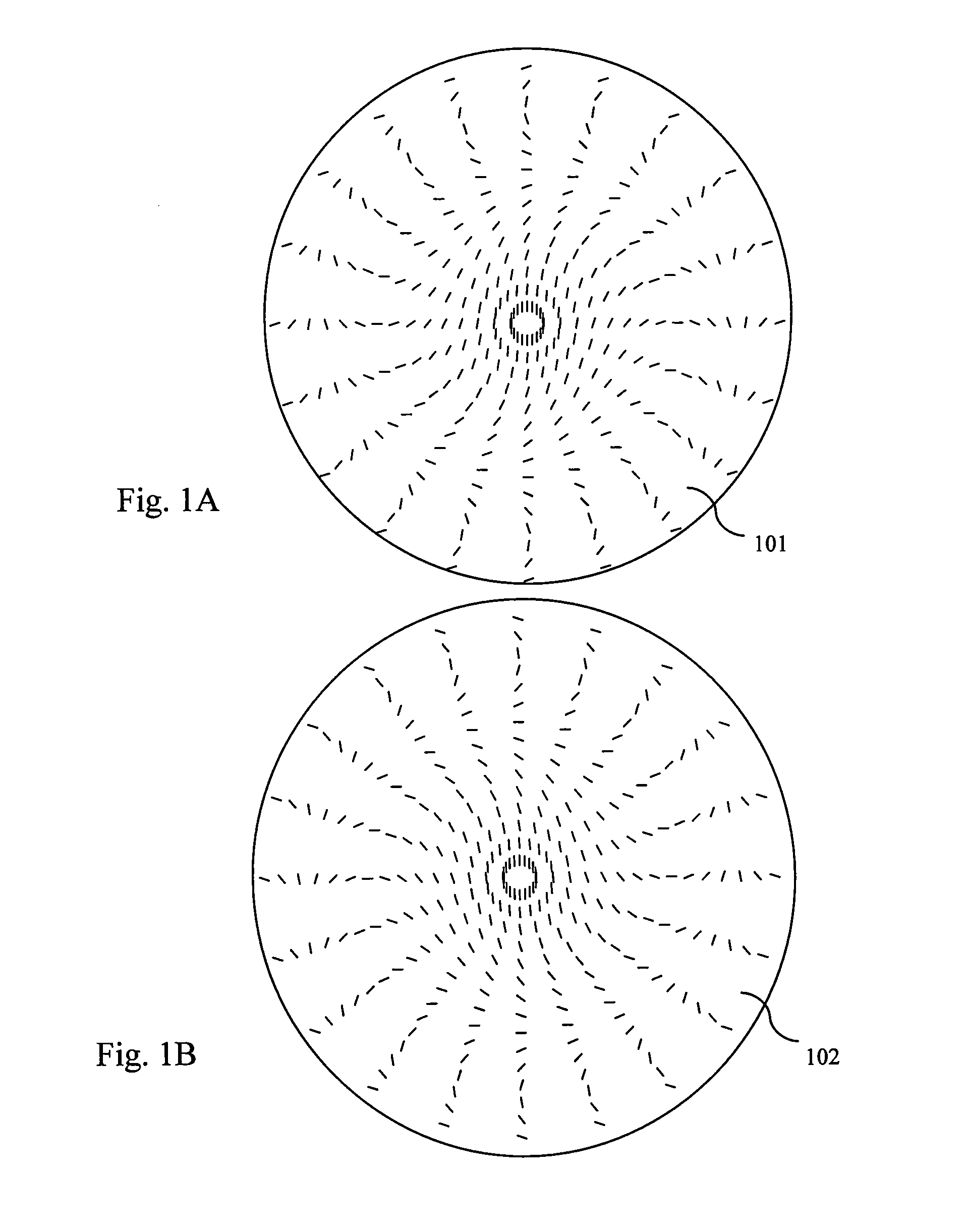
  • Diffractive Waveplate Lenses for Correcting Aberrations and Polarization-Independent Functionality
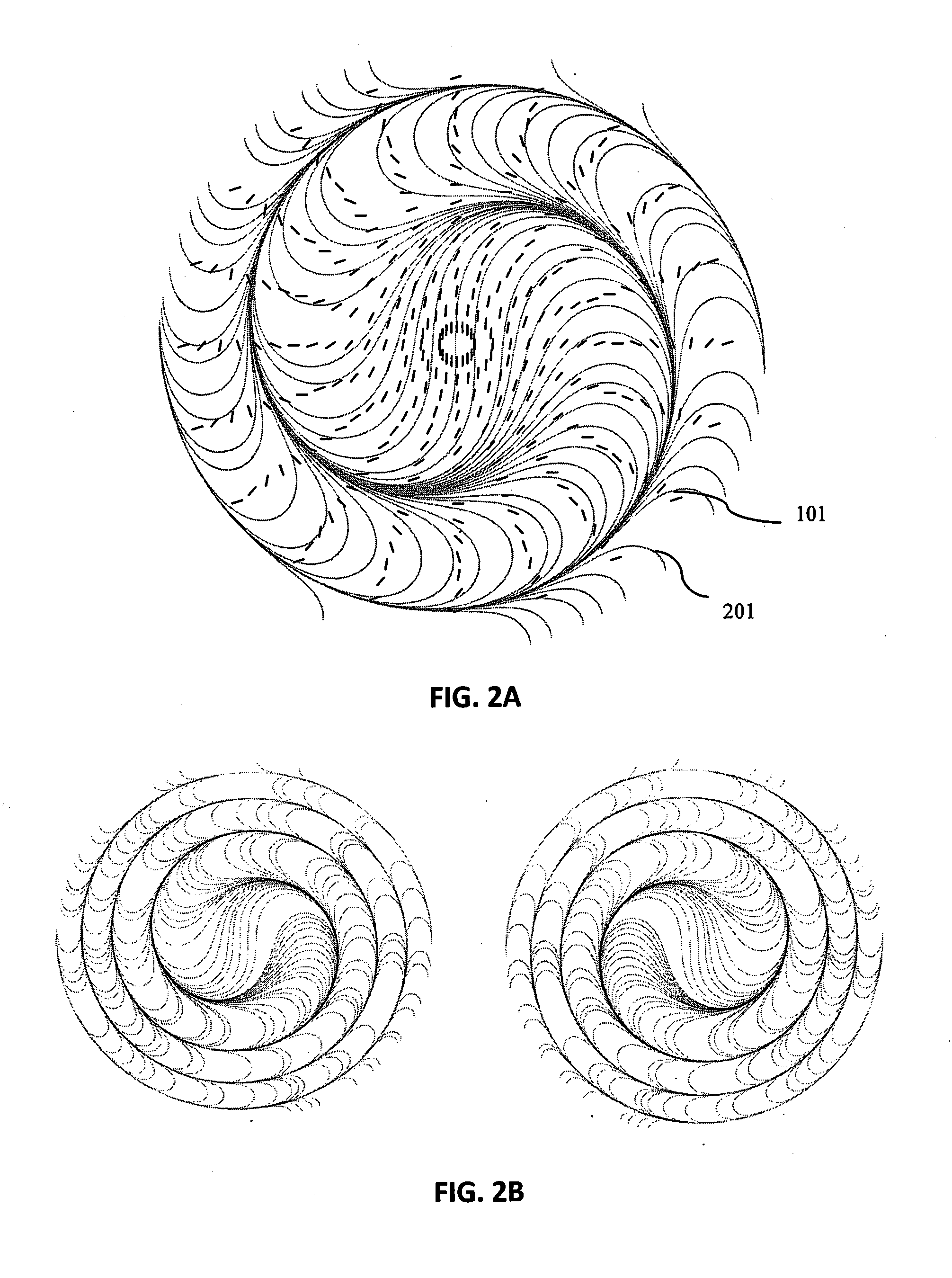
  • Diffractive Waveplate Lenses for Correcting Aberrations and Polarization-Independent Functionality

Examples


Embodiment Construction

[0036]Before explaining the disclosed embodiments of the present invention in detail it is to be understood that the invention is not limited in its applications to the details of the particular arrangements shown since the invention is capable of other embodiments. Also, the terminology used herein is for the purpose of description and not of limitation. In the Summary above and in the Detailed Description of Preferred Embodiments and in the accompanying drawings, reference is made to particular features (including method steps) of the invention. It is to be understood that the disclosure of the invention in this specification includes all possible combinations of such particular features. For example, where a particular feature is disclosed in the context of a particular aspect or embodiment of the invention, that feature can also be used, to the extent possible, in combination with and / or in the context of other particular aspects and embodiments of the invention, and in the inve...


PUM


Abstract

Diffractive waveplate lenses, devices, systems and methods of fabricating and manufacturing lenses for correcting spherical and chromatic aberrations of diffractive waveplate lenses and refractive lenses, by using nonlinear patterning of anisotropy axis of birefringent layers comprising the diffractive waveplate lenses, and their combinations and for obtaining polarization-independent functionality of diffractive waveplate lenses.

Description

CROSS REFERENCE TO RELATED APPLICATIONS[0001]This application claims the benefit of priority to U.S. Provisional Application Ser. No. 61 / 980,062 filed Apr. 16, 2014, the entire application of which is incorporated by reference in its' entirety.GOVERNMENT LICENSE RIGHTS[0002]This invention was made with government support under Army Contract No. W911QY-12-C-0016. The government has certain rights in this invention.FIELD OF THE INVENTION[0003]This invention relates to optical lenses, and in particular to lenses, systems, devices, and methods of manufacturing and fabricating lenses, applications of the lenses, and combinations of said lenses, useful for imaging optics and systems, astronomy, displays, polarizers, optical communication and other areas of laser and photonics technology.BACKGROUND OF THE INVENTION[0004]The present invention is in the technical field of optics. More particularly, the present invention is in the technical field of lenses. Lenses are commonly made by shaping...

Claims


Application Information

Patent Timeline
Patent Type & Authority Applications(United States)
IPC IPC(8): G02B5/30G02B5/18G02B27/42
CPCG02B5/1833G02B5/3083G02B27/4216G02B27/4211G02C7/086G02C2202/16G02C2202/20G02B3/10A61F2/1618G02C7/022G02C7/061G02C7/10G02C7/12A61F2/1654G02B5/001G02B5/1828G02B6/024G02B6/3534G02B6/3592G02B3/0081G02B27/4205G02B27/4261
Inventor TABIRIAN, NELSON V.ROBERTS, DAVID E.STEEVES, DIANE M.KIMBALL, BRIAN R.
Owner U S ARMY NATICK SOLDIER RES DEV & ENG CENT
Learn More