Permanent-magnet ac power generator

a permanent magnet ac and generator technology, applied in the direction of synchronous generators with multiple outputs, magnetic circuit rotating parts, magnetic circuit shapes/forms/construction, etc., can solve the problems of increasing the demand for electric power, increasing the need for power up and down sizing, and difficulty in constant voltage control, so as to reduce the flow of magnetic flux, reduce the effect of electromotive voltage and effective technology

Active Publication Date: 2016-02-11
KAWAMURA MEGUMI
View PDF5 Cites 5 Cited by
  • Summary
  • Abstract
  • Description
  • Claims
  • Application Information

AI Technical Summary

Benefits of technology

The purpose of this invention is to make the power of a permanent magnet generator increase using a simple technique while keeping it small in size. By controlling the current flow in multiple windings, the invention creates a compound magnetic force that interacts with the permanent magnetic force of each phase, resulting in a stronger torque and increased driving force for the motor. This results in a double increase in the driving force for the motor.

Problems solved by technology

But, as the voltage of permanent magnet generator increases in proportion to revolution speed because of having constant magnetic force, the voltage raises too much at high speed conditions and it is very difficult to control the voltage constantly.
Moreover, the demand of electric power is increasing very much therefore power up and down sizing are required more and more.
However, the electric generator has a problem that it is very difficult to get high power at low speed condition because the magnetic power of the rotor is too low.
However, the increase of generator size is also limited and a shortage of generating power is very big problem for drivers because of experience battery die.
In addition, the permanent magnet generators for the vehicle have been studied to realize many times, however, the size of the generator became too large in order to get necessary power, and they have not succeeded in developing a generator with extreme small size, then, they have given up to install the permanent magnet generator into vehicles.
However, it is very difficult to increase the electric power in the permanent magnet generator having compact size and simple controller and there are nothing a practicable and epoch-making technology.
In addition, it is possible to use the IPMSM for generator, but the control system is very complicate and the control system have to consisted by many parts, as the result, the cost of the system become very expensive.
Especially, IPMSM used much rear earth has a defect because it become very expensive.
However, it is difficult to increase the electromotive voltage and power even if they change many kind of winding method in the conventional winding methods, which is clear as shown in equation 1 and 2.
According to studying the equation 3, as there is no method reducing the inductance L drastically without changing the winding number, it is clear that it is difficult to make the power of generator increase without increasing the size of it.

Method used


Image

  • Permanent-magnet ac power generator
  • Permanent-magnet ac power generator
  • Permanent-magnet ac power generator

Examples


Embodiment Construction

[0055]A structure of permanent-magnet AC generator having the plurality windings to increase power with small size with the present invention will be herein-after described with reference to the accompany drawing.

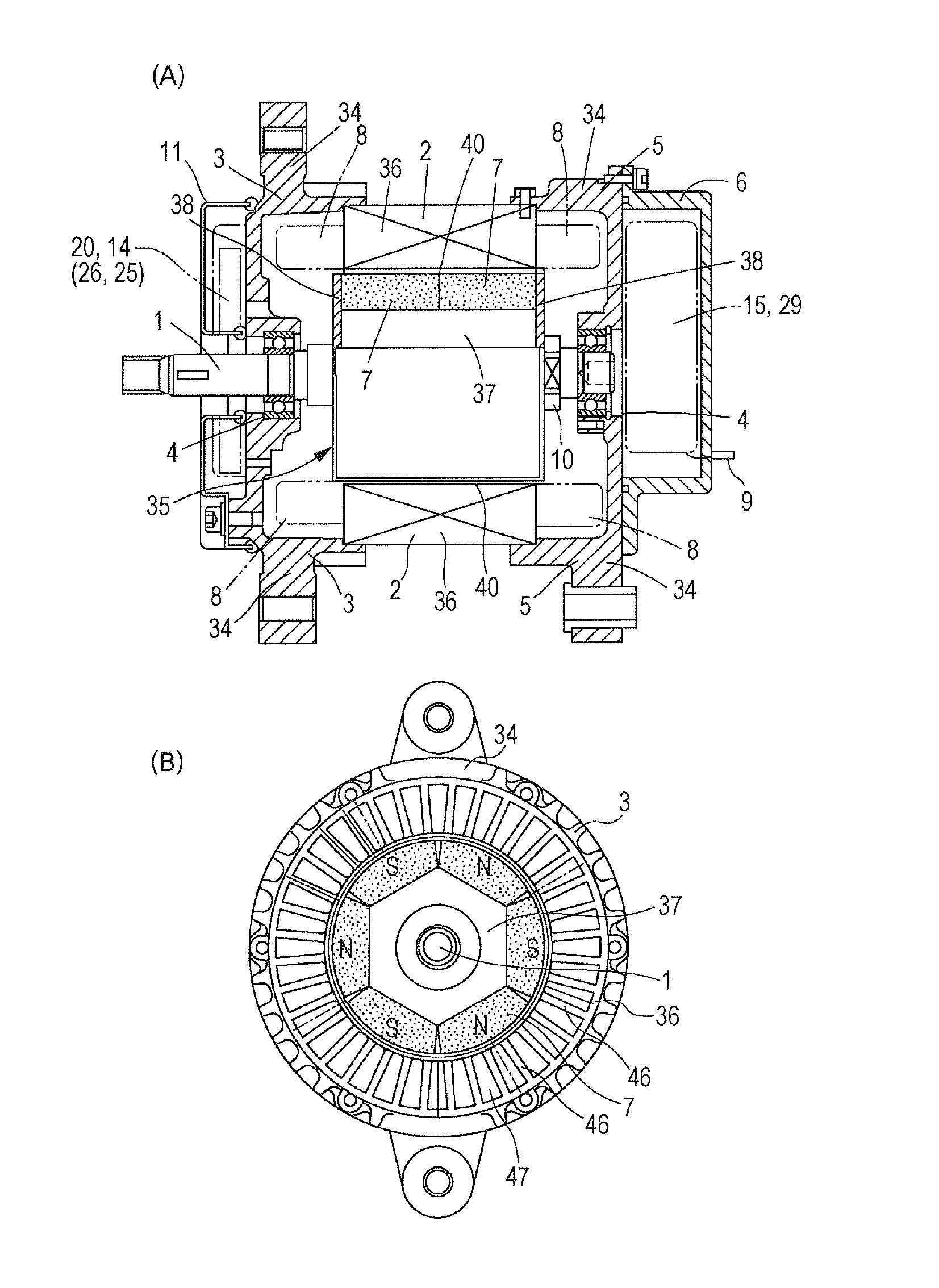
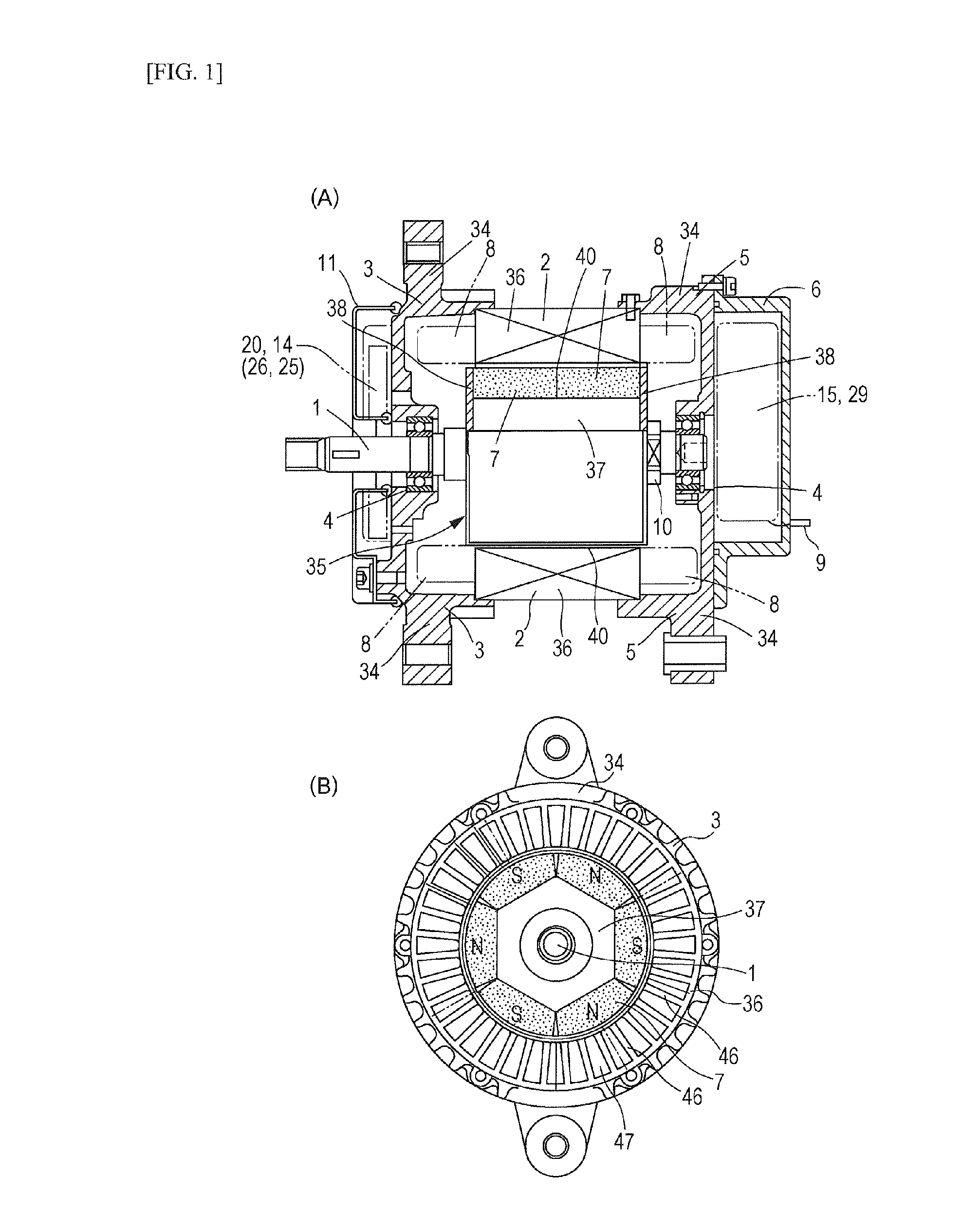
[0056]The one of embodiments of the permanent-magnet AC generator is shown as FIG. 1 in accordance with the patent invention. The embodiment of the permanent-magnet AC generator is having 6 poles and three phases and the AC generator as shown in FIG. 1 is comprised of stator housing 34 which is pair of housing halved housing 3 and 5, a rotor shaft 1 supported for rotation in the housing 3 and 5 by means of pair of axially opposite ball bearing 4, a rotor 35 of multi-polar permanent magnet member 7 in which more than one pair of permanent magnet pieces is arranged circumferentially around the rotor shaft 1, a stator 2 arranged around the outer periphery of the rotor 35. The stator 2 is composed by stator core 36 and rolled up by electromagnetic coils 8 arranged in stator cor...


PUM


Abstract

The present invention relates to a plurality windings of U phase corresponding to one magnetic pole including first and second windings wound in a short pitch winding manner. The winding starts of the first and second windings are shifted by at least one tooth. The windings are wound so that a winding angle occupied by the windings inter-slot angle from the winding start of the first winding to the winding end of the second winding corresponds to a pole angle. The windings in the V phase are disposed in the same relationship as in the U phase at the position delayed by an electric angle of 120 degrees with respect to the U phase, and those in the W phase are disposed at the position delayed by an additional 120 degrees. The outputs of the windings are then each rectified, subsequently joined together and used by adding currents.

Description

CROSS REFERENCE TO RELATED APPLICATIONS[0001]This application is a U.S. National Phase Application under 35 U.S.C. §371 of International Patent Application PCT / JP2013 / 005139 filed Aug. 30, 2013, which claims priority to Japanese Patent Application No. 2012-190249 filed Aug. 30, 2012. The[0002]International Application was published on Mar. 6, 2014, as International Publication No. WO 2014 / 034136 under PCT Article 21(2). The entire contents of these Applications are hereby incorporated herein by reference.TECHNICAL FIELD[0003]The present invention relates to a stator winding of permanent-magnet AC generator including a stator attached to a housing, and a rotor provided with permanent magnet members that rotate wish respect the stator.BACKGROUND ART[0004]Conventionally, the permanent magnet materials have been adopted for the rotor of generator in order to improve the efficiency. The strong point of the permanent magnet generator has high power in spite of low speed conditions because...

Claims


Application Information

Patent Timeline
IPC IPC(8): H02K3/28H02K1/27H02K11/00H02K11/04H02K21/00
CPCH02K3/28H02K1/2786H02K21/00H02K11/046H02K11/0094H02K21/48H02P9/02H02K11/05H02K1/2791
Inventor KAWAMURA, HIDEO
Owner KAWAMURA MEGUMI
Why Eureka
Try Eureka