A system for recovering and converting kinetic energy and potential energy as electrical energy for an aircraft

a technology of electrical energy and potential energy, applied in the field of aircraft electrical energy generator system, can solve problems such as excessive fuel consumption in engines

Active Publication Date: 2016-02-04
SAFRAN ELECTRICAL & POWER
View PDF1 Cites 13 Cited by
  • Summary
  • Abstract
  • Description
  • Claims
  • Application Information

AI Technical Summary

Benefits of technology

[0011]With the electrical energy generator system of the invention, there is no longer any need to increase engine speed above its normal speed during the stage of descent, thus making it possible on each flight to save 1% to 3% of fuel consumption, depending on the level reached and the speed at the end of cruising.
[0014]In both circumstances, the air admission elements are totally integrated in the shell of the system when they are in the closed position, thereby not increasing drag as a result of local turbulence.
[0017]According to a fifth characteristic of the invention, the turbine has variable pitch blades, thus making it possible to control the speed of rotation of the turbine as a function of the speed of the air stream striking the turbine, and thus making it possible to regulate the frequency of the electricity generator.
[0019]In a first aspect of the aircraft of the invention, it includes a control device for causing the air admission means to open automatically, at least during a stage of the aircraft descending. The aircraft may thus have an additional source of electrical energy available during stages of descent without needing to increase engine speed as is commonly done during such a stage.

Problems solved by technology

Nevertheless, and paradoxically, during stages of descent, the pilot is often obliged to increase engine speed in order to have sufficient energy for pressurizing and conditioning cabin air and also for running electrical devices on board.
That solution is not satisfactory since it leads to excessive fuel consumption in the engines even though they are operating at low speed during this stage of flight (descent).

Method used


Image

  • A system for recovering and converting kinetic energy and potential energy as electrical energy for an aircraft
  • A system for recovering and converting kinetic energy and potential energy as electrical energy for an aircraft
  • A system for recovering and converting kinetic energy and potential energy as electrical energy for an aircraft

Examples


Embodiment Construction

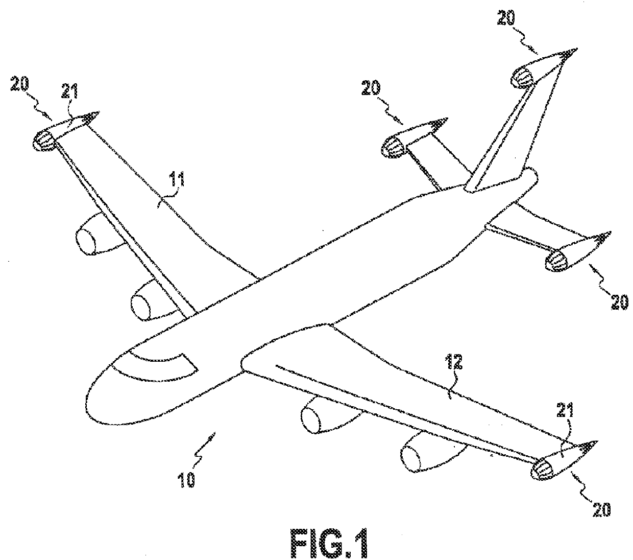
[0028]FIG. 1 shows an airplane 10 that includes, in accordance with an embodiment of the invention, two electrical energy generator systems 20 placed respectively at the ends of wings 11 and 12. Each system 20 comprises a streamlined fairing 21 corresponding in this example to a shell having the shape of a wing tip tank and of the same type as those fitted to the ends of airplane or missile wings in order to reduce or “break” turbulence (vortices) at the wing tip and reduce the interfering aerodynamic drag due to such turbulence. The shape of the fairing is essentially that of a wing tip tank or an ovoid that is tapered to a greater or lesser extent depending on the size and the shape of the wing on which the system of the invention is to be mounted. Any other shape serving to reduce aerodynamic drag could be used. In addition, or instead of two electrical energy generator systems 20 placed at the ends of wings, the airplane could also have one or more systems 20 placed at the ends ...


PUM


Abstract

The invention relates to an electrical energy generator system (20) for an aircraft (10), the system comprising a streamlined fairing (21) containing at least one turbine (22) housed in the front portion (21a) of the fairing (21), and an electrical energy generator (23) connected to said turbine. The front portion (21a) of the fairing (21) is fitted with air admission means (26) that are movable between an open position in which the turbine (22) is exposed to the stream of air outside the fairing (21) and a closed position in which the turbine (22) is masked inside the fairing (21). The invention serves to reduce the aerodynamic drag usually caused by turbulence present at a wing tip for a conventional wing having sharp edges during stages of takeoff, climbing, and cruising; and during stages of descent it makes it possible to recover the kinetic and potential energy that has been accumulated by the aircraft during its stages of climbing and cruising.

Description

BACKGROUND OF THE INVENTION[0001]The present invention relates to generating electrical energy in aircraft by recovering kinetic energy and potential energy.[0002]When an airplane gains on altitude and speed, it increases its kinetic energy Ec and its potential energy Ep, which can be calculated respectively from the following formulas:Ec=½mv2 Ep=mghwhere m is the mass of the airplane, v is the speed of the airplane, g is acceleration due to gravity (9.81 m / s2) and h is the height of the airplane relative to the ground.[0003]During a stage of climbing, the airplane increases its speed so as to go from a takeoff speed of about 230 kilometers per hour (km / h) to a cruising speed lying in the range approximately 500 km / h to 800 km / h (Mach 0.82 to 0.84), thereby enabling it to accumulate a very large amount of kinetic energy. Concerning potential energy, present airplanes cruise at an altitude of about 12,000 meters (m).[0004]During a stage of descent, because of the kinetic energy and t...

Claims


Application Information

Patent Timeline
Patent Type & Authority Applications(United States)
IPC IPC(8): B64D41/00F03D1/04F03D1/06F03D9/00
CPCB64D41/007F03D1/06B64D2041/002F03D9/002F03D9/02F03D1/04B60K16/00B64D41/00F05B2220/31F03D9/10F03D9/25Y02E10/72Y02E10/728Y02E70/30Y02T50/50F03D9/00F03D9/11F03D9/32
Inventor ROQUES, SERGE
Owner SAFRAN ELECTRICAL & POWER
Why Eureka
Try Eureka