
Self-aligned spatial filter

a spatial filter and self-aligning technology, applied in the field of spatial filters, can solve the problems that the spatial filter does not lend itself well to optically based consumer electronics devices, and achieve the effects of ensuring high performance, reliability and stable performance, and quick fabrication of spatial filter modules

Inactive Publication Date: 2016-01-28
INTEGRATED PLASMONICS CORP
View PDF4 Cites 26 Cited by
  • Summary
  • Abstract
  • Description
  • Claims
  • Application Information

AI Technical Summary

Benefits of technology

This patent describes a way to quickly make spatial filter modules in different shapes and sizes. These filters can be made in single or multiple lenses, and can be used for various applications such as optical instruments and consumer health monitoring devices. The position of the optical elements is fixed, ensuring reliable and stable performance. Overall, this invention allows for efficient and effective fabrication of spatial filters.

Problems solved by technology

Such existing spatial filters do not lend itself well for an optically based consumer electronics device where fast volume production is generally necessary.

Method used


Image

  • Self-aligned spatial filter
  • Self-aligned spatial filter
  • Self-aligned spatial filter

Examples


Embodiment Construction

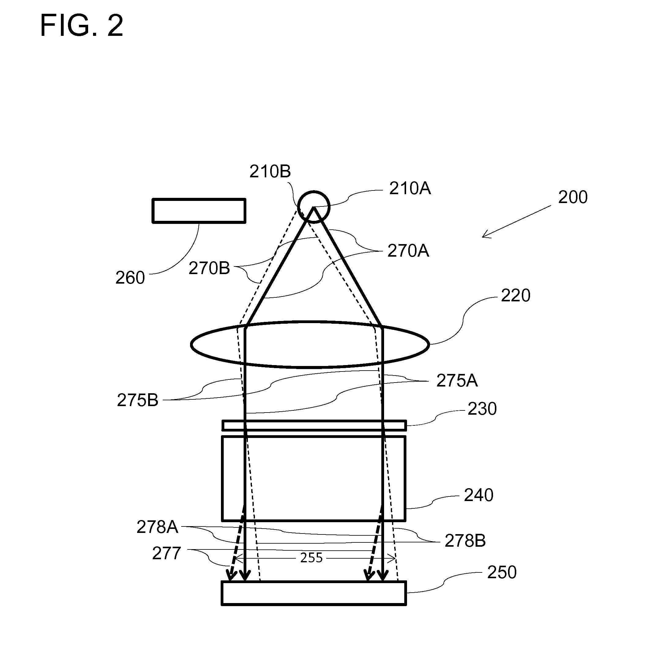
[0023]Embodiments are described in detail with reference to the drawings. Features and structures contained in attached drawings are schematic representations of embodiments of the present invention and are not drawn to scale; relative dimensions of the features and structures depicted are not accurate. In particular, for ease of explanation and illustration, even in the same drawings, some of the features or structures are exaggerated or magnified by one or more orders of magnitudes as compared with other features of the drawings.

[0024]In typical absorption spectroscopic analysis of an analyte, probing light of a certain bandwidth is configured to interact with the analyte. The analyte absorbs some components of the probing light. The spectrum of the light transmitted through the analyte is compared with the spectrum of the probing light to quantitatively and qualitatively measure properties of the analyte.

[0025]In order to analyze the spectrum of the transmitted light in a small, ...


PUM

PropertyMeasurementUnit
wavelengthaaaaaaaaaa

Abstract

A spatial filter is made by forming a structure comprising a focusing element and an opaque surface, the opaque surface being disposed remotely from the focusing element in substantially the same plane as a focal plane of the focusing element; and by forming a pinhole in the opaque surface at or adjacent to a focal point of the focusing element by transmitting a substantially collimated laser beam through the focusing element so that a point optimally corresponding to the focal point is identified on the opaque surface and imperfection of the focusing element, if any, is reflected on the shape and position of the pinhole so formed.

Description

BACKGROUND[0001]1. Field of the Invention[0002]This invention relates to a spatial filter, and more particularly, to a spatial filter adequate for implementation in compact optical devices, such as personal health-monitoring devices for distributed healthcare and point-of-care consumer health monitoring devices and to manufacture methods therefor.[0003]2. Description of the Related Art[0004]Micro or sub-millimeter scale pinholes are typically used as spatial filters in precision optical scientific instruments such as interferometers, alignment and inspection instrumentation to perform such functions such as cleaning up laser beam spatial profiles or collimating a finite sized light source in a desired direction. They typically require minimally 3 degrees of freedom with micro-scale resolution and a skilled technician or engineer to align. Such existing spatial filters do not lend itself well for an optically based consumer electronics device where fast volume production is generally...

Claims


Application Information

Patent Timeline
Patent Type & Authority Applications(United States)
IPC IPC(8): G02B27/46B23K26/384B23K26/402C23C14/34C25D5/02G01N21/31
CPCG02B27/46G01N21/31B23K26/384C23C14/34B23K2203/18B23K26/402G01N2201/068G01N2201/0633C25D5/02B23K2103/18B23K2103/50G01N21/255
Inventor SHAGAM, MICHAEL YAGODAWALTERS, ROBERT JOSEPH
Owner INTEGRATED PLASMONICS CORP
Learn More