Insect trap using UV LED lamp

a technology of ultraviolet light and insect trap, which is applied in the direction of insect traps and killers, semiconductor devices, electrical equipment, etc., can solve the problems of short span, high power consumption and heat generation, environmental pollution, etc., and achieve the effect of increasing the efficiency of insect trapping

Active Publication Date: 2016-01-28
SEOUL VIOSYS CO LTD
View PDF16 Cites 10 Cited by
  • Summary
  • Abstract
  • Description
  • Claims
  • Application Information

AI Technical Summary

Benefits of technology

[0009]Various embodiments are directed to an insect trap using, in place of a conventional UV lamp, a UV LED lamp that increases the insect trapping efficiency.

Problems solved by technology

However, such conventional lamps all have problems in that the power consumption and heat generation are high, the life span is short, and toxic gas filled therein causes environmental pollution.
However, the production cost of LED packages that emit light in the UV range is considerably higher than the production cost of LED packages that emit light in the visible range, and various products using UV LED packages have not been developed since the characteristics of UV light is quite different from the characteristics of light in the visible range.
In addition, even when a UV LED is applied to a conventional UV light source lamp product instead of the UV light source lamp, the conventional UV light source lamp product does not exhibit its effect in many cases, because the light-emission characteristics of the UV LED differ from those of the conventional UV light source lamp.
For this reason, if a UV lamp in a conventional insect trap is simply replaced with a UV LED, there is a problem in that the insect trapping effect can decrease rather than increase.
This may reduce the mobility of electrons, thereby increasing the recombination rate of electrons and holes in the active region.

Method used


Image

  • Insect trap using UV LED lamp
  • Insect trap using UV LED lamp
  • Insect trap using UV LED lamp

Examples


1st embodiment

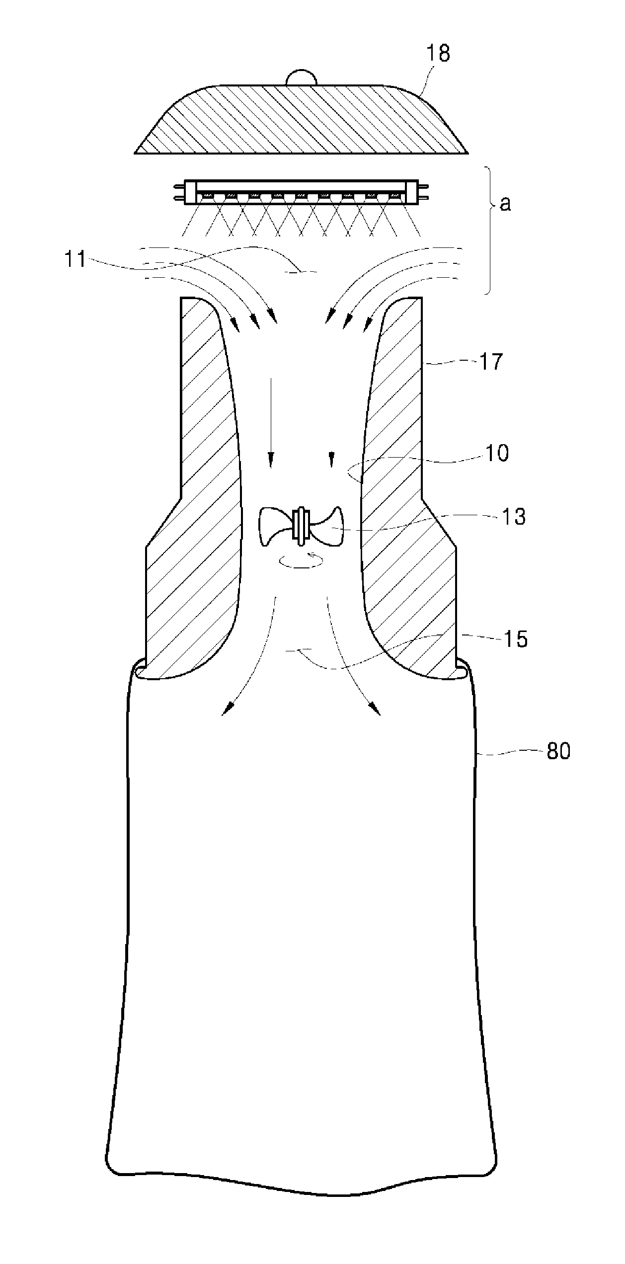
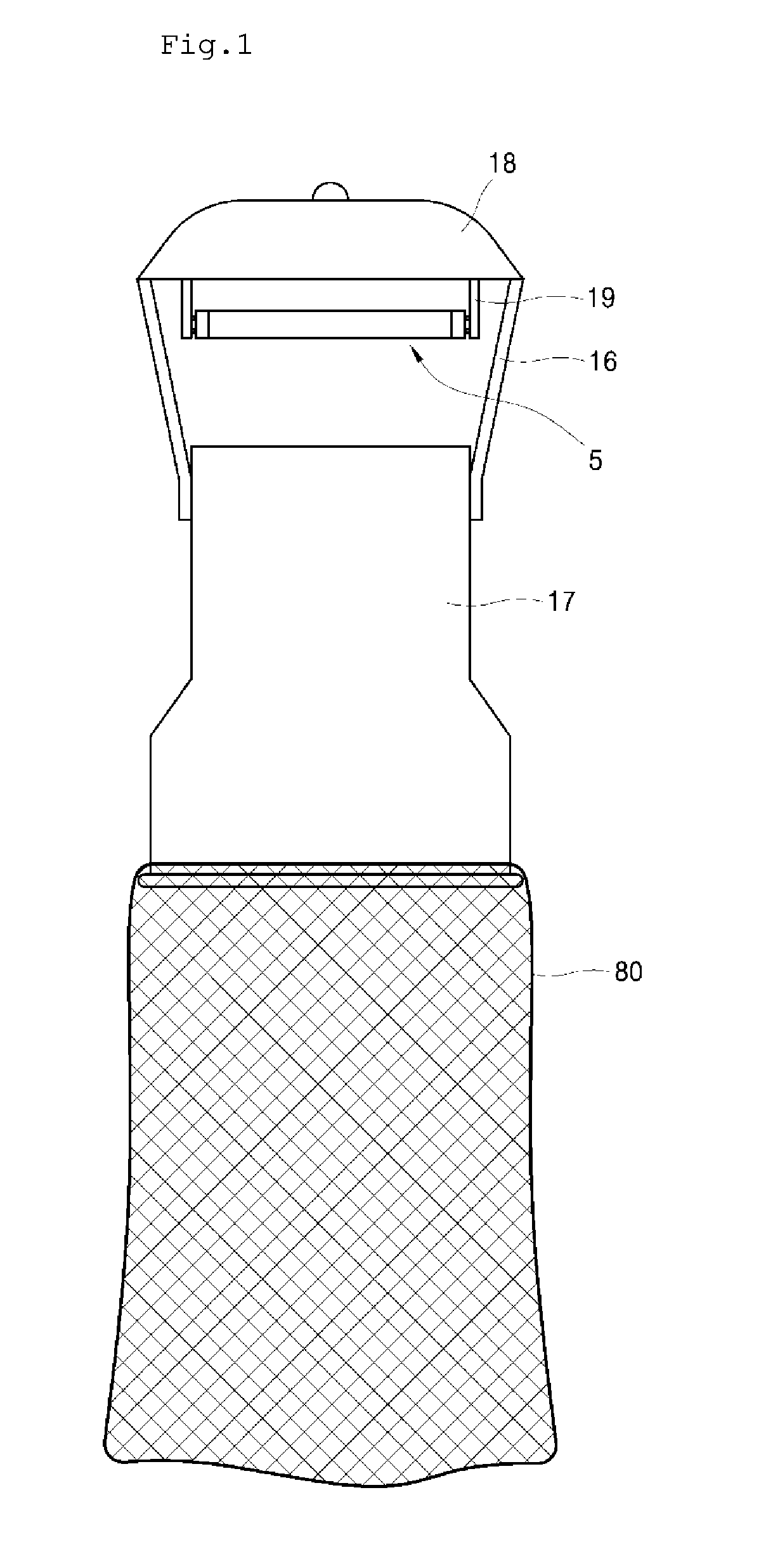
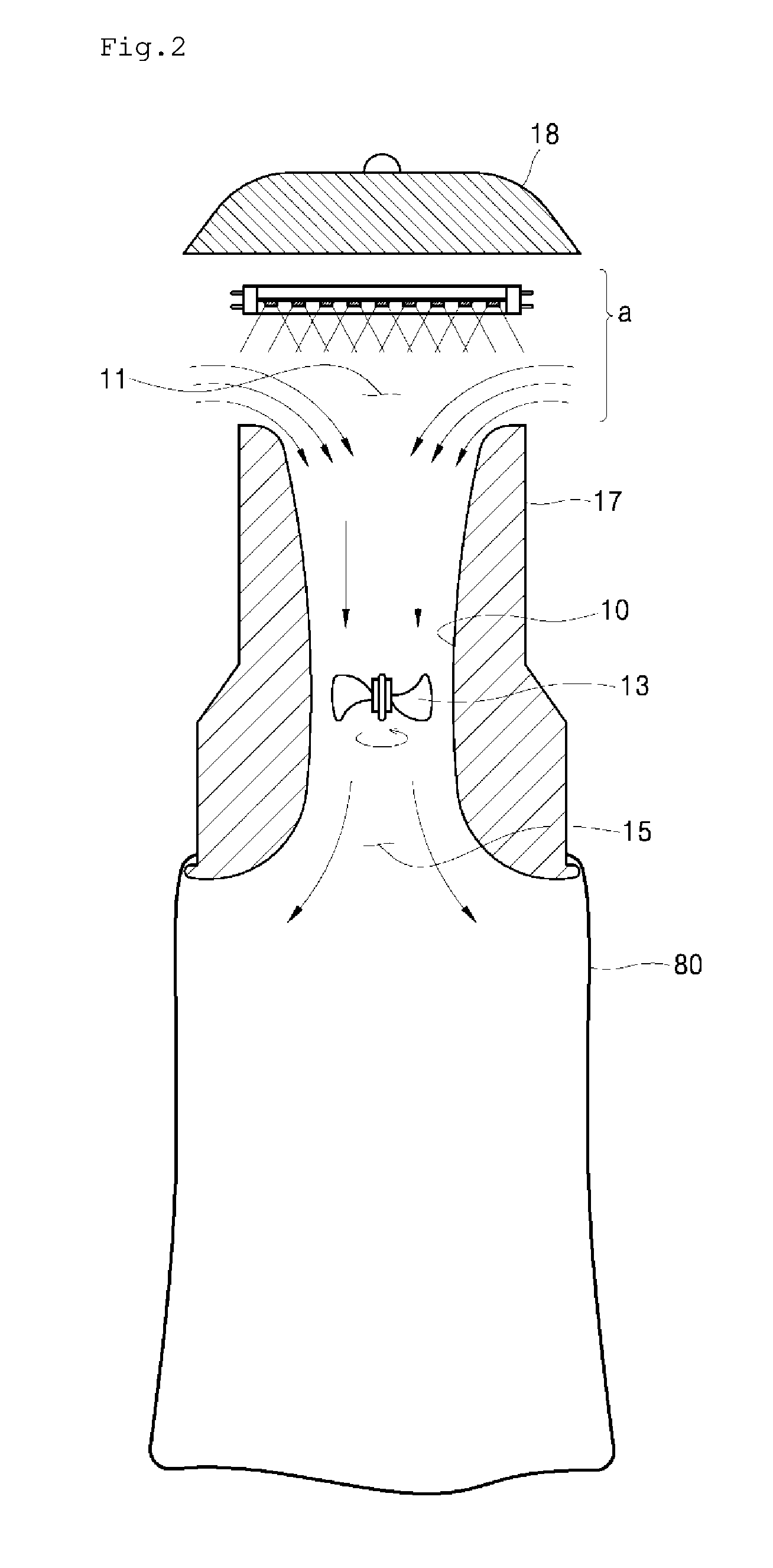
[0047]FIG. 1 is a side view of an insect trap according to the present disclosure, FIG. 2 is a side cross-sectional view of the insect trap according to the present disclosure, and FIG. 3 is an enlarged view of a portion of a UV LED lamp used in the insect trap of the present disclosure.

[0048]The insect trap of the present disclosure includes a second housing 18 formed in a cover shape at the top of the insect trap, a first housing 17 disposed below the second housing 18 so as to be spaced apart therefrom, and a plurality of elongate connecting members 16 configured to fix the second housing 18 and the first housing 17 to each other in a spaced state.

[0049]A lamp support unit 19 is disposed at the bottom of the second housing 18, and a UV LED lamp 5 is supported thereby and is electrically connected to a power source. As shown in FIG. 2, the UV LED lamp 5 supported by the lamp support unit 19 is located in the spacing “a” between the first housing 17 and the second housing 18 so as ...

2nd embodiment

[0064]FIG. 4 is a perspective view of an insect trap according to the second embodiment of the present invention. The insect trap shown in FIG. 4 is a product named Luralite made by P&L Systems Ltd. The same UV LED lamp as the first embodiment is used for the second embodiment. The UV LED lamp is installed so as to emit UV light upwardly as seen in FIG. 4. UV light does not have to be emitted upwardly, but it is desirable that the UV LED lamp is installed so as not to emit the UV light directly toward human bodies in the living space.

[0065]The experiments are performed in the cases that radiant flux of the UV LED lamps are different, that UV light is uniformly surface-emitted from the housing of the UV LED lamp roughened by sand blast process or is spot-emitted directly from the chips of the UV LED lamp, and that the wavelength of UV light of the UV LED lamps are different.

experiment 1

[0066]The 1st experiment is attractant competition between 500 mW and 1,000 mW of radiant flux for uniformalized 365 nm LED UV lights using Luralite traps against house flies (Musca domestica) in a dark laboratory condition.

[0067]House fly collection rates were compared between 500 mW and 1,000 mW with uniformalized 365 nm LED UV lights using Luralite traps against 50 Musca domestica. The experiment site was a screened enclosure (1.8×3.7×1.8 m) in a dark laboratory. The experiments were conducted the paired tests in simultaneous exposure conditions for 1, 2, 4, 8, and 12 hours from the morning, Room Temp.: 27±1° C., RH: 64±4%, 2 replicates.

[0068]The collection rates of 1,000 mW for uniformalized 365 nm LED UV lights were significantly higher than those of 500 mW against house flies at 8 and 12 hour exposure periods (see Table 1). As a result, 1,000 mW radiant flux for uniformalized 365 nm LED UV lights was more effective than 500 mW for house fly light traps.

TABLE 3Comparisons of co...


PUM


Abstract

The present disclosure relates to an insect trap using an ultraviolet light-emitting diode (UV LED) lamp, and more particularly, to an insect trap using, in place of a conventional UV light source lamp, a UV LED lamp that significantly increases the insect trapping efficiency. The insect trap according to the present disclosure includes: a UV LED lamp disposed in an air inlet portion of the duct, and including a printed circuit board (PCB) that has a UV LED chip mounted thereon; an installing portion for installing the UV LED lamp on; and a trapping portion provided near the installing portion.

Description

BACKGROUND[0001]1. Technical Field[0002]The present disclosure relates to an insect trap using an ultraviolet light-emitting diode (UV LED) lamp, and more particularly, to an insect trap using, in place of a conventional UV light source lamp, a UV LED lamp that significantly increases the insect trapping efficiency.[0003]2. Related Art[0004]UV light sources have been used for medical purposes such as sterilization, disinfection and the like, the purpose of analysis based on changes in irradiated UV light, industrial purposes such as UV curing, cosmetic purposes such as UV tanning, and other purposes such as insect trapping, counterfeit money discrimination and the like.[0005]Conventional UV light source lamps that are used as such UV light sources include mercury lamps, excimer lamps, deuterium lamps and the like. However, such conventional lamps all have problems in that the power consumption and heat generation are high, the life span is short, and toxic gas filled therein causes ...

Claims


Application Information

Patent Timeline
Patent Type & Authority Applications(United States)
IPC IPC(8): A01M1/08A01M1/04A01M1/10H01L33/04H01L33/06H01L33/14H01L33/32H01L33/38H01L33/48
CPCA01M1/04H01L33/06H01L33/32H01L33/14A01M1/08H01L33/38H01L33/486A01M1/106H01L33/04H01L33/26
Inventor KOO, JONG HYUNSONG, HYUN SULEE, DONG-KYU
Owner SEOUL VIOSYS CO LTD
Why Eureka
Try Eureka