Manufacturing method of substrate structure, substrate structure and metal component

Active Publication Date: 2016-01-14
WISTRON NEWEB
View PDF5 Cites 0 Cited by
  • Summary
  • Abstract
  • Description
  • Claims
  • Application Information

AI Technical Summary

Benefits of technology

The invention provides a method for making a substrate structure by forming a passivation layer on the surface of a metal substrate using a simple process called submerging. This method prevents the formation of extra metal layers and reduces the consumption of chemical plating solution while also avoiding poor appearance caused by the extra metal layer.

Problems solved by technology

These metal components have active metal surfaces, and therefore, in the case of producing metal pattern during electroless plating process, it may often happen that extra metal layers are adhered to the metal components, which causes an increased plating costs and a risk of short circuit.
For example, in the case that extra metal layers attached on the thread surface of the metal nut, the metal layers plated on the metal nut through electroless plating may be squeezed and falling down when other members are assembled to the metal nut, which results in a short circuit.
Further, when the metal pattern is also formed on a non-predetermined area, it may not only increase the amount of the plating bath but also result in a poor appearance problem.
However, with an extra charge is applied, the plating bath becomes unstable and the risk of plating out is also increased.
In addition, expensive fixtures are needed when the above-mentioned anti-plating method is performed.

Method used


Image

  • Manufacturing method of substrate structure, substrate structure and metal component
  • Manufacturing method of substrate structure, substrate structure and metal component
  • Manufacturing method of substrate structure, substrate structure and metal component

Examples


Embodiment Construction

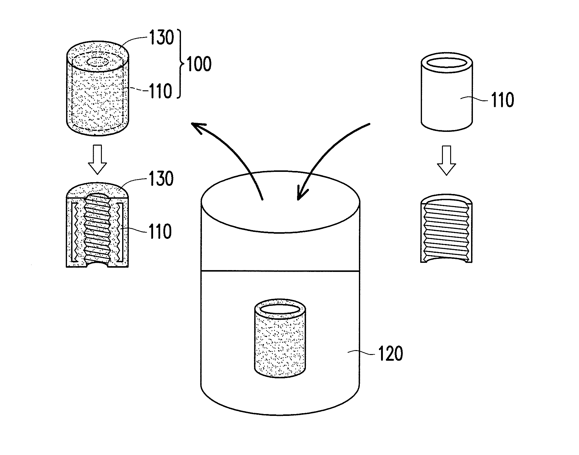
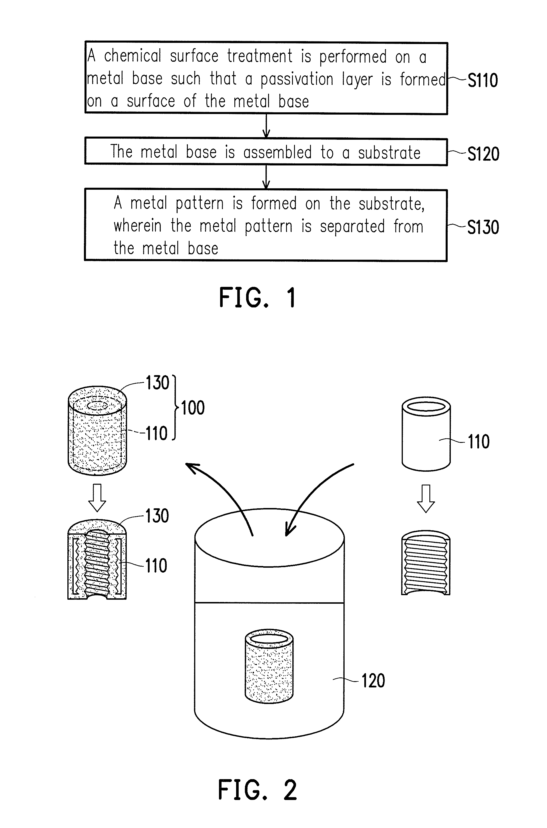
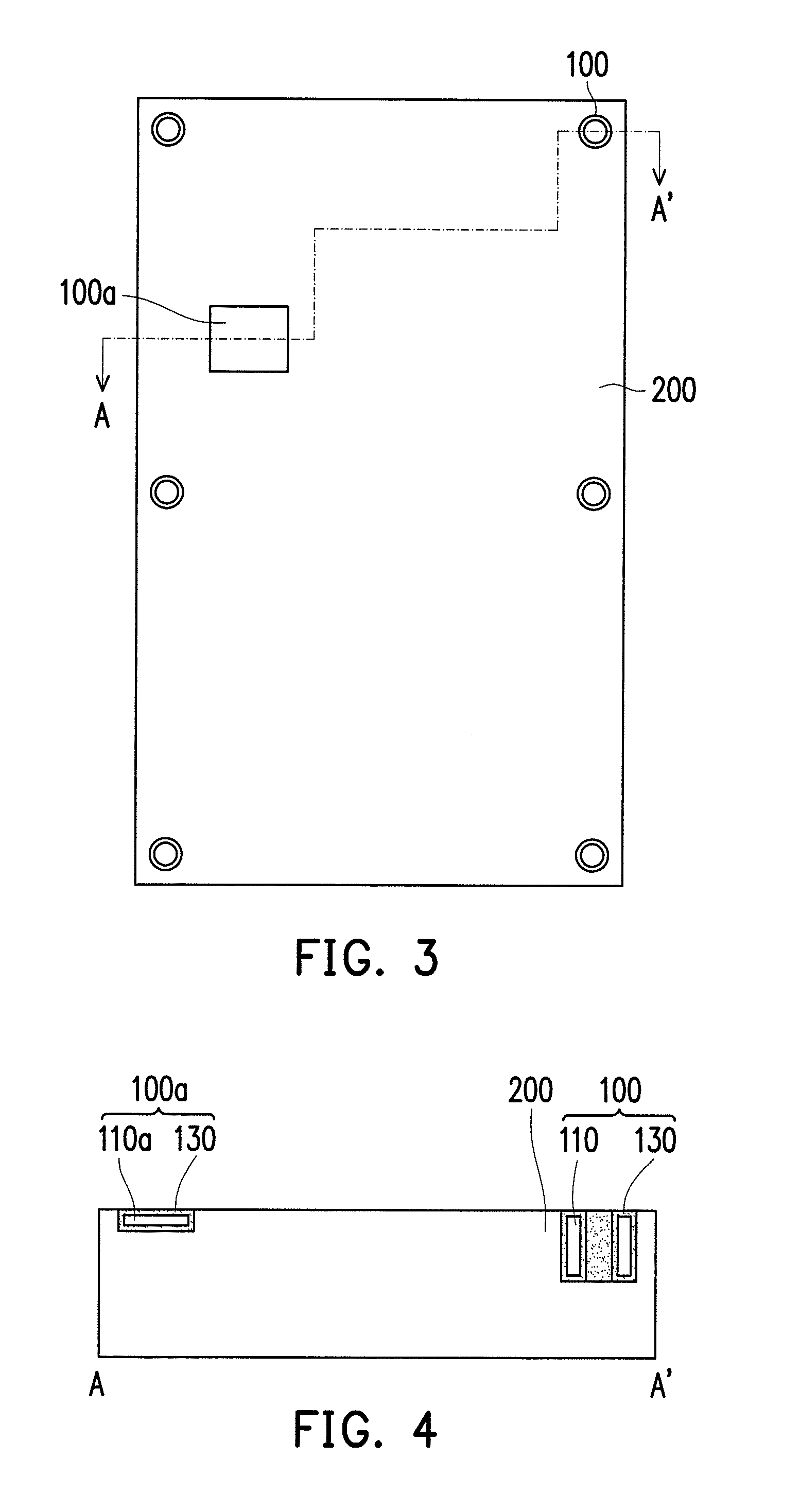
[0024]FIG. 1 is a flowchart illustrating manufacturing steps of the substrate structure according to an embodiment of the invention. FIG. 2 to FIG. 6 are diagrams illustrating manufacturing steps of the substrate structure. FIG. 4 is a cross-sectional schematic of FIG. 3. FIG. 6 is a cross-sectional schematic of FIG. 5. First, referring to FIG. 1 and FIG. 2, in step S110, a chemical surface treatment is performed on a metal base 110. The chemical surface treatment is, such as submerging the metal base to a solution of the thiol compound 120, so as to form a passivation layer 130 on the surface of the metal base 110, wherein the element showing under the metal base 110 at right side in FIG. 2 is a cross-section view of the metal base 110 while the element showing under the metal component 100 at left side in FIG. 2 is a cross-section view of the metal component 100.

[0025]The metal base 110 may be a metal insert disposed on the substrate (such as chassis, circuit board, etc.), and the...


PUM


Abstract

A manufacturing method of a substrate structure including the following steps is provided. A chemical surface treatment is performed on a metal base such that a passivation layer is formed on a surface of the metal base. The metal base is assembled to a substrate. A metal pattern is formed on the substrate, wherein the metal pattern is separated from the metal base. A substrate structure and a metal component are also provided.

Description

CROSS-REFERENCE TO RELATED APPLICATION[0001]This application claims the priority benefit of Taiwan application serial no. 103124155, filed on Jul. 14, 2014. The entirety of the above-mentioned patent application is hereby incorporated by reference herein and made a part of this specification.BACKGROUND OF THE INVENTION[0002]1. Field of the Invention[0003]The invention generally relates to a manufacturing method of substrate structure, a substrate structure, and a metal component, and in particular, to a manufacturing method of substrate structure, a substrate structure, and a metal component, wherein the substrate structure has passivation layers.[0004]2. Description of Related Art[0005]For the circuit board and the antenna application, the specific electroless plating is used to form the metal plating pattern on the plastic substrate. However, the plastic substrate itself is often associated with other metal components which are provided, such as, a metal nut or a metal insert and ...

Claims


Application Information

Patent Timeline
IPC IPC(8): H05K3/18H05K1/02H05K1/09H05K3/46
CPCH05K3/181H05K3/46H05K1/0296H05K1/09C23C18/1603C23C18/1605C23C18/32C23C18/38C23C18/42C23C18/48C23C22/02C25D5/34H05K3/384H05K3/387H05K3/389C23C18/165
Inventor CHUANG, TZU-WENRADI, BABAKCHEN, SHIH-HONGCHEN, CHUN-LIN
Owner WISTRON NEWEB
Why Eureka
Try Eureka