
Ice Auger Assembly Incorporating an Ice Reaming Blade

a technology of reaming blades and ice augers, which is applied in the field of ice augers, can solve the problems of broken edge of hole, damage to fish, and loss of prize fish of the day,

Active Publication Date: 2016-01-14
IVAN SR ERIC JOHN
View PDF11 Cites 9 Cited by
  • Summary
  • Abstract
  • Description
  • Claims
  • Application Information

AI Technical Summary

Benefits of technology

The present invention is for an improved ice auger that has a reaming blade assembly. This assembly can be easily activated and deactivated using a spring biased latch while the auger is in use. The reaming blade smooths the sharp edge of the hole and flare the lower portion of the hole in one operation. Additionally, the invention provides an ice reaming blade that can be easily sharpened, repaired or replaced as needed. The invention also includes vertical stabilizing posts to prevent wobble while the auger is in use. Overall, this invention simplifies the process of drilling ice holes and improves the efficiency of ice removal.

Problems solved by technology

Often, the line, stretched at a right angle and rubbing against the sharp edge of the hole is broken and the prize fish of the day is lost.
A fish may be pulled hard against the edge and injured or the hook dislodged from its mouth and again lost.
Or, it may be difficult to turn a large fish into the narrow hole and again the fish may be injured or lost.
The reamer blade of this device appears to be sufficient size to smooth the edge of the hole, but is too narrow to provide a widened or funnel shaped opening.

Method used


Image

  • Ice Auger Assembly Incorporating an Ice Reaming Blade
  • Ice Auger Assembly Incorporating an Ice Reaming Blade
  • Ice Auger Assembly Incorporating an Ice Reaming Blade

Examples


Embodiment Construction

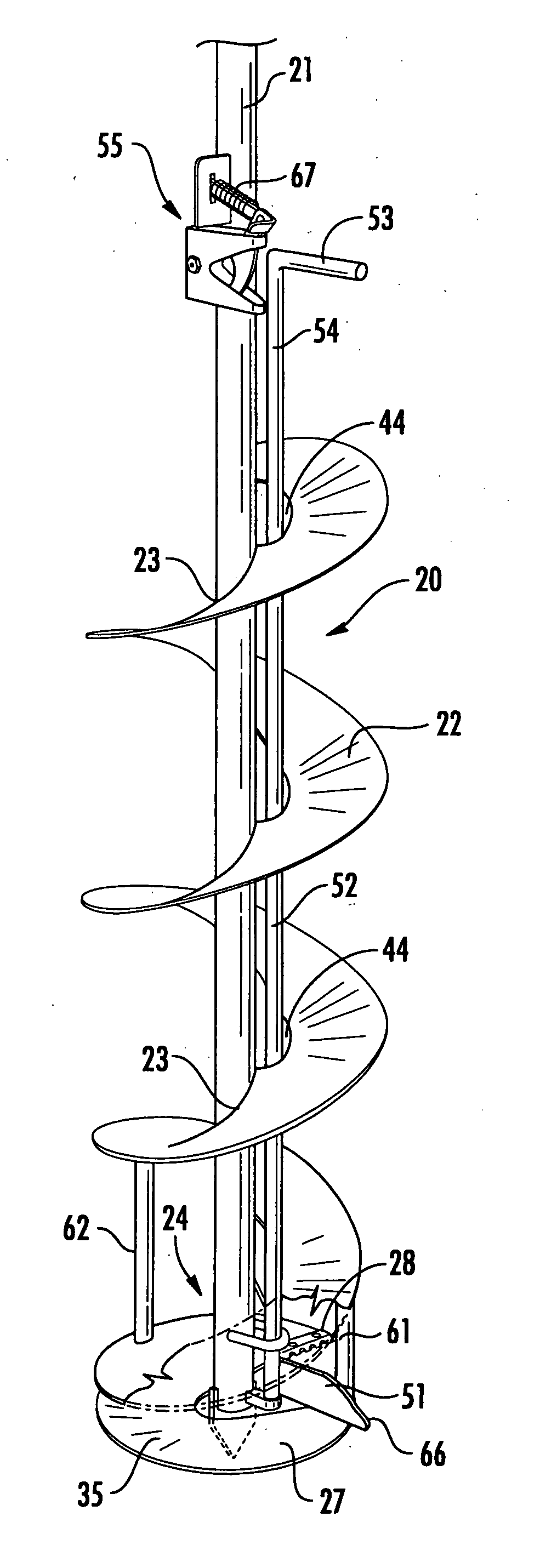
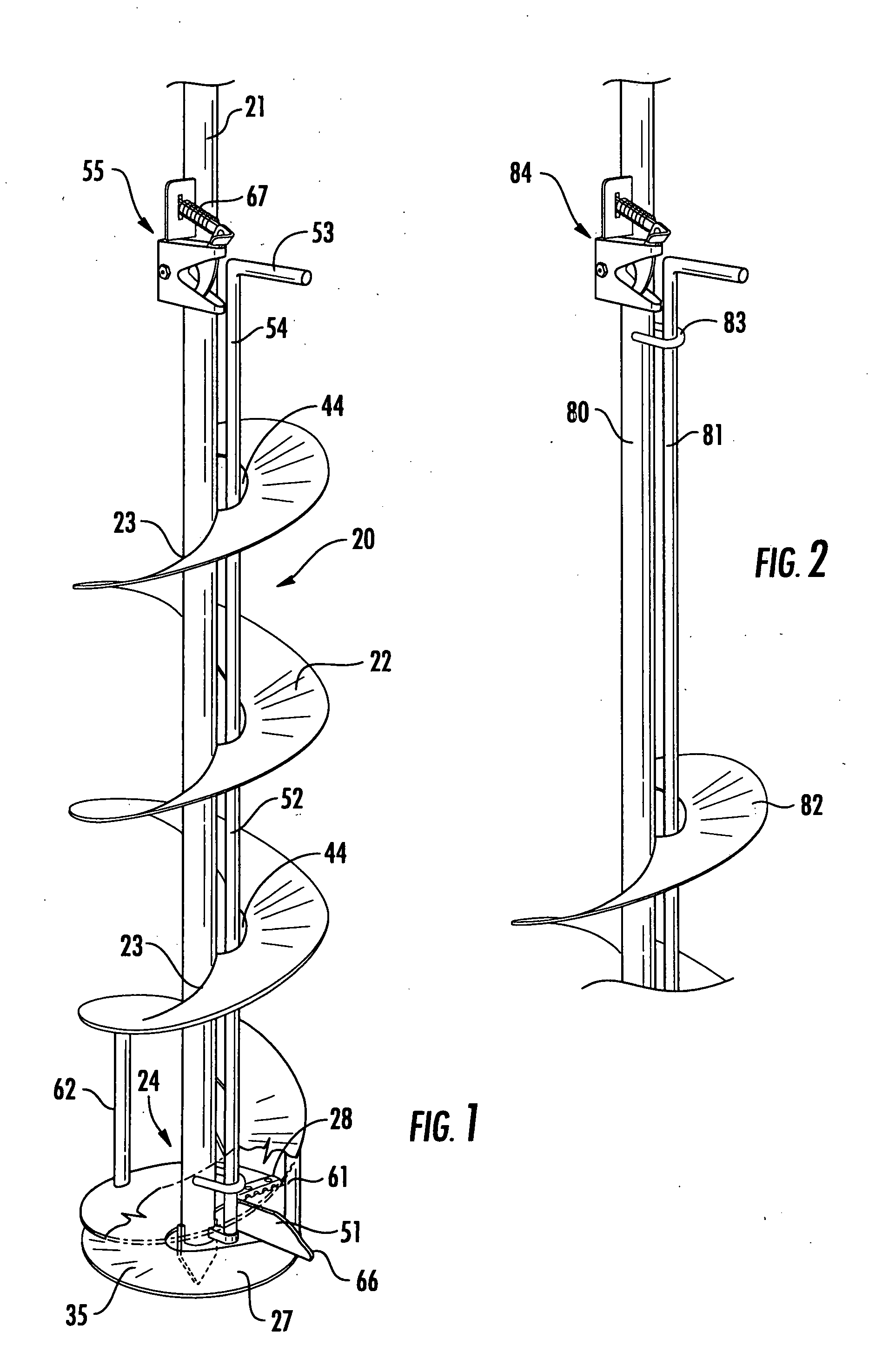
[0032]Ice augers currently in use may generally have a central shaft of tubular construction encircled by a helical blade or fighting running substantially along the lower three quarters of the length of the central shaft. The helical blade may be welded to the shaft along the inside edge. An ice cutting blade may be reversibly attached to the leading edge of the helical blade which may be substantially coextensive with the lower end of the central shaft. The ice chips produced by the ice cutting blade may be transported to the surface by the helical blade. An attachment means may be located at the top of the central shaft by which a hand crank or motor may be attached to the central shaft to rotate the auger.

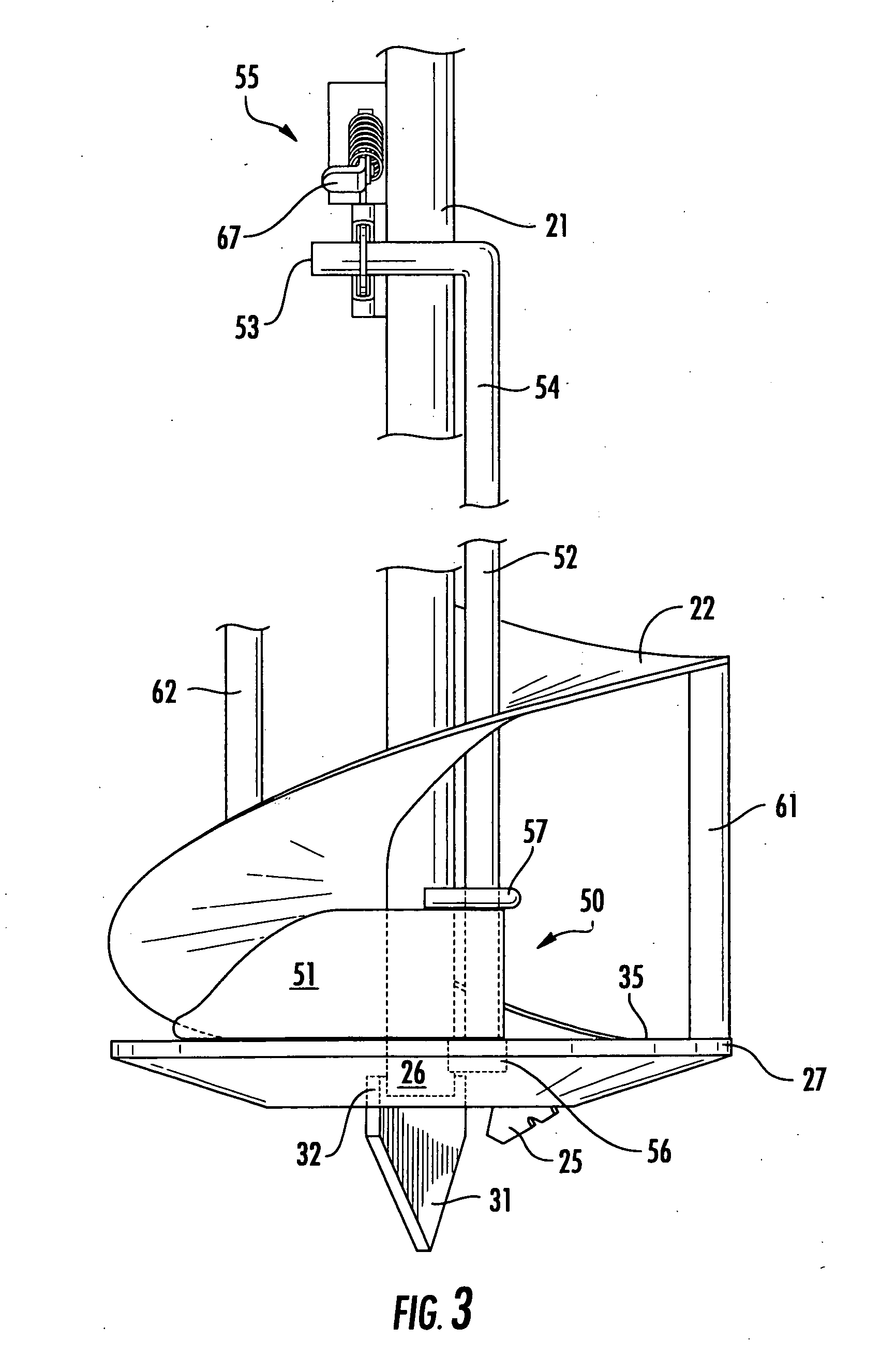
[0033]The ice auger 20 ideally suited to the present invention and illustrated in FIG. 1 may have the tubular central shaft 21 and the helical blade 22 attached to the central shaft 21 along its inside edge 23. There may also be a metal concave split ring 27 of heavier construc...


PUM


Abstract

An ice auger has a rotatable rod adjacent and parallel to the central shaft supported at the bottom in a cylindrical receptacle. A vertical ice reaming blade is attached to the rod above the receptacle and a retaining loop affixed to the shaft and positioned above the blade prevents the rod from rising out of the receptacle. A right angled handle at the top of the rod extends outward above and in the same plane as the blade. A spring biased latch assembly disposed near the top of the shaft engages the handle with the blade in rest position. Releasing the latch frees the rod to rotate 180° and move the blade to use position extending outward beyond the standard auger members to ream the bottom of the ice hole. Vertical support posts stabilize the system and prevent wobble. One post functions as a stop and back support for the blade during use.

Description

FIELD OF THE INVENTION[0001]The instant invention relates to ice augers and more specifically ice augers equipped with a reaming blade to remove the sharp bottom edge and flare the lower portion of the ice hole.BACKGROUND OF THE INVENTION[0002]From early times man has devised ways to break through the ice to reach the water below for his personal needs and to catch the fish dwelling in the body of water. The first patent for an ice auger issued to Clark in 1873 (U.S. Pat. No. 139,769). Today, ice fishing has become a major winter pastime evoking the creativity of the fishermen in devising more efficient means to insure the retrieval of their catch. Ice augers themselves have not changed appreciably in recent years, but though they are capable of drilling through ice layers of from several inches to more than five feet, the resulting hole always has a sharp edge at its bottom. Once a fish has been caught, the line must be played and the fish drawn up through the relatively narrow hol...

Claims


Application Information

Patent Timeline
Patent Type & Authority Applications(United States)
IPC IPC(8): E21B7/00
CPCE21B7/008A01K97/01E21B10/327E21B10/44E21B10/26E21B10/32E21B7/28
Inventor IVAN, SR., ERIC, JOHN
Owner IVAN SR ERIC JOHN
Learn More