
Enhanced Visualisation of Geologic Features in 3D Seismic Survey Data

Active Publication Date: 2016-01-07
FOSTER FINDLAY ASSOCS
View PDF1 Cites 4 Cited by
  • Summary
  • Abstract
  • Description
  • Claims
  • Application Information

AI Technical Summary

Benefits of technology

The patent text describes a method for analyzing seismic data by looking at the reflections that occur when a source of sound waves shakes the ground. These reflections are then recorded by a receiver. The method eliminates certain distortions that can occur in the data, making it easier to analyze. This also helps to combine the data from different parts of the ground more accurately. The technical effect is better quality seismic data with fewer distortions.

Problems solved by technology

However, any one attribute that highlights faults typically does so in an incomplete way, only capturing certain characteristics of the fault expression within the seismic data, and even combining multiple attributes is not sufficient to accurately characterise and distinctively visualize geologic features such as faults in a 2D or 3D seismic survey data volume.
However, despite the improvements in highlighting geological features, such as faults, using attribute algorithms for several different attributes derivable from typical 3D seismic survey data, currently available software tools are still relatively unreliable when detecting and representing complex geological features.
Also, typical attribute algorithms are often very sensitive to strata patterns, causing interferences between the visual extraction of the “wanted” geologic features (e.g. faults) and the “unwanted” geologic features (e.g. horizons).

Method used


Image

  • Enhanced Visualisation of Geologic Features in 3D Seismic Survey Data
  • Enhanced Visualisation of Geologic Features in 3D Seismic Survey Data
  • Enhanced Visualisation of Geologic Features in 3D Seismic Survey Data

Examples


Embodiment Construction

)

[0060]The exemplary embodiments of this invention will be described in relation to interpretation of 3D seismic data. However, it should be appreciated that, in general, the system and method of this invention will work equally well for any other type of 3D data from any environment.

[0061]For purposes of explanation, it should be appreciated that the terms ‘determine’, ‘calculate’ and ‘compute’, and variations thereof, as used herein are used interchangeably and include any type of methodology, process, mathematical operation or technique, including those performed by a system 400, as depicted in a simplified form in FIG. 15. The terms ‘generating’ and ‘adapting’ are also used interchangeably describing any type of computer modelling technique for visual representation of a subterranean environment from geological survey data, such as 3D seismic data. In addition, the terms ‘vertical’ and ‘horizontal’ refer to the angular orientation with respect to the surface of the earth, i.e. a...


PUM


Abstract

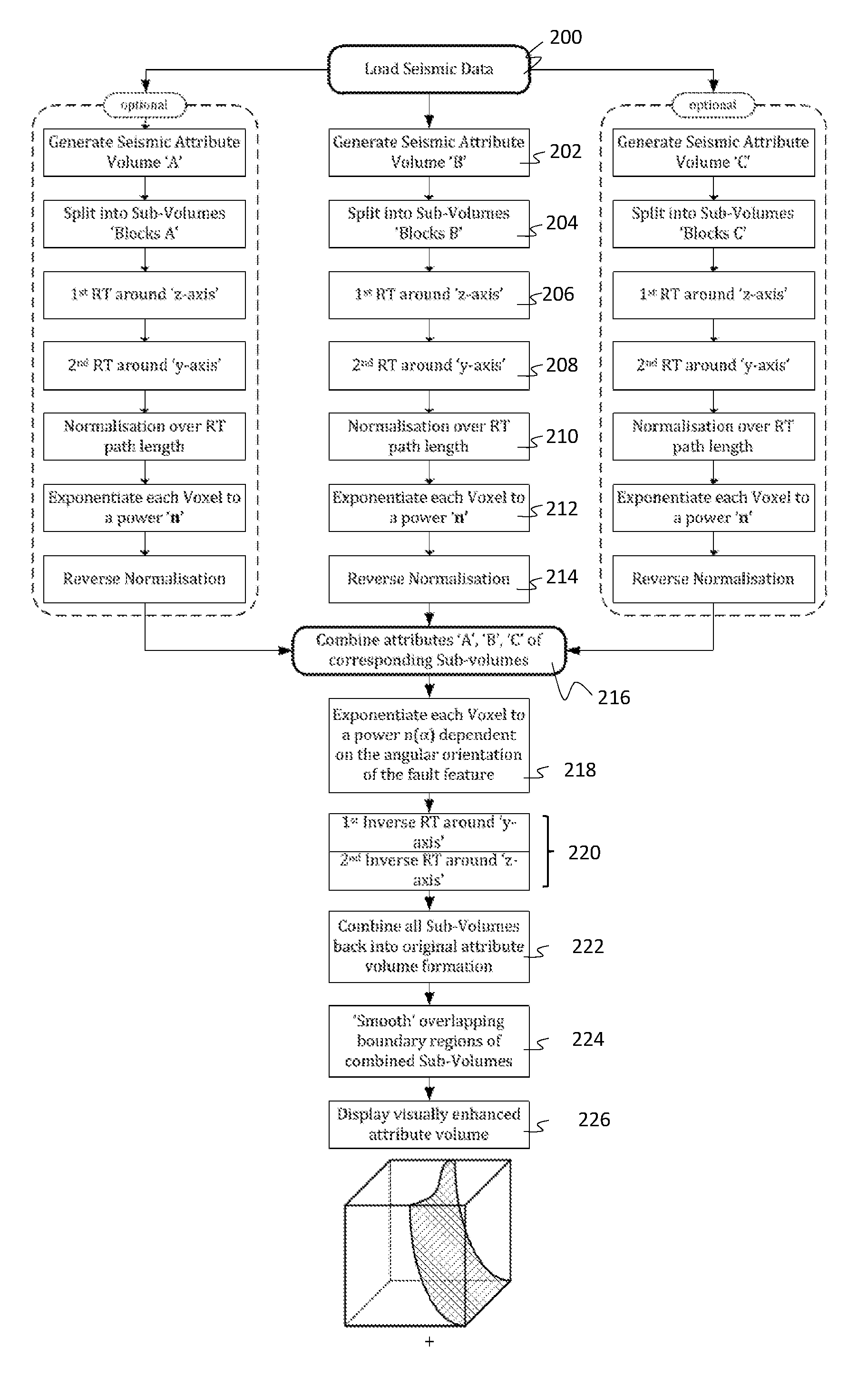
A method of visually enhancing at least one geologic feature in 3D seismic survey data, comprising the steps of: (a) generating at least one attribute volume definable in Cartesian space and comprising at least one attribute derivable from said 3D seismic survey data; (b) generating a first Radon data volume from data resulting from a transaxial Radon Transform of said at least one attribute volume with respect to a first Cartesian axis; (c) generating a second Radon data volume from data resulting from a transaxial Radon Transform of said first Radon data volume with respect to a second Cartesian axis; (d) generating a third Radon data volume from data resulting from exponentiating a characteristic parameter of each one of a plurality of voxels forming said second Radon data volume to a predetermined first power value, and (e) applying a first Inverse Radon Transform to said third Radon data volume with respect to said second Cartesian axis, and a subsequent second Inverse Radon Transform to the resulting data from said first Inverse Radon Transform with respect to said first Cartesian axis.

Description

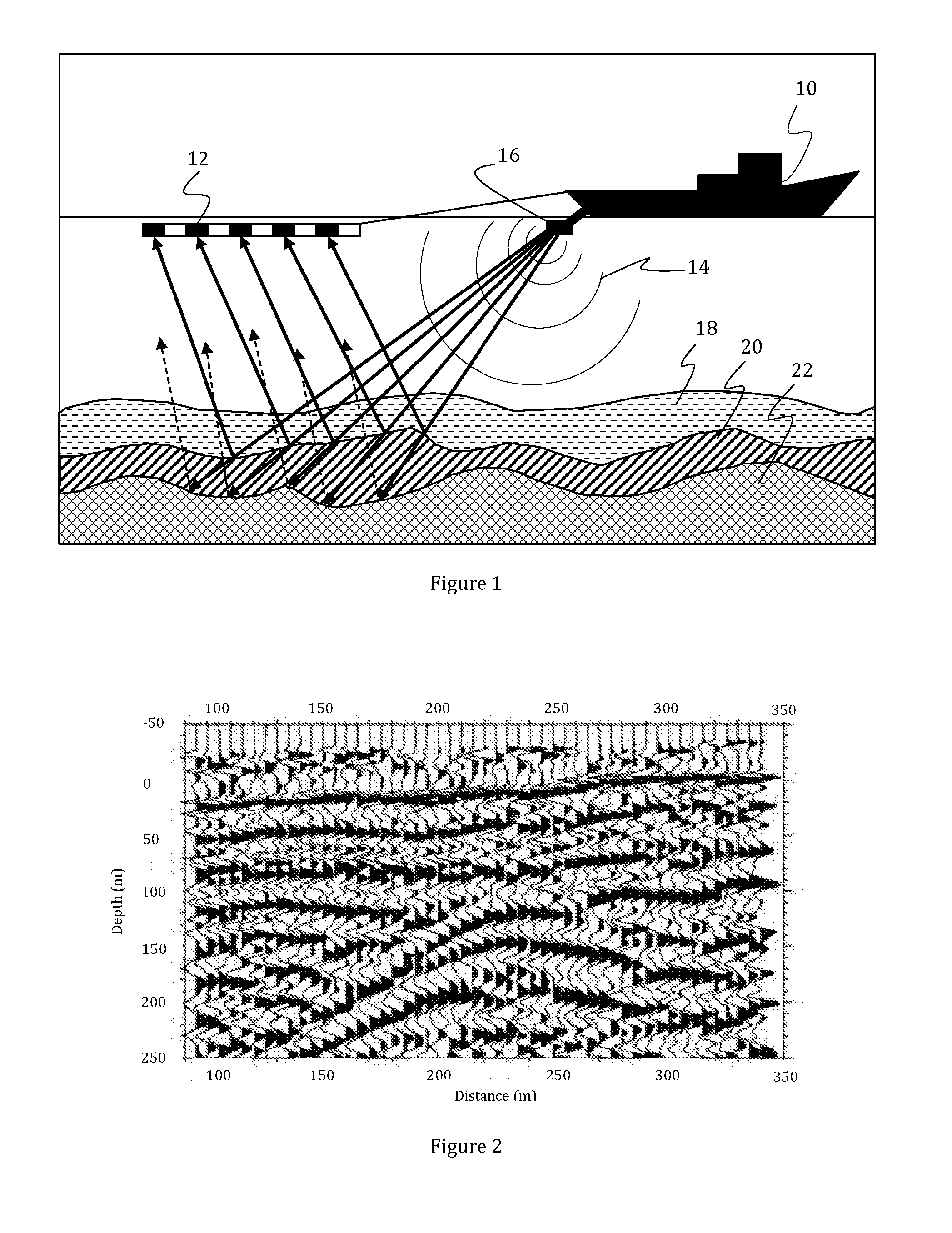
[0001]The present invention relates generally to the field of oil and gas exploration, and in particular to the field of computer aided exploration for hydrocarbons using geophysical data, such as for example seismic data, of the earth. In particular, the present invention relates to the visual enhancement of geologic features, such as faults, in a seismic volume generated from at least one attribute.INTRODUCTION[0002]In the oil and gas industry, geological data surveys such as, for example, seismic prospecting and other similar techniques are commonly used to aid in the search for and evaluation of subterranean hydrocarbon deposits. As an example, prospecting operations include three basic stages (i) data acquisition, (ii) data processing and (iii) data interpretation. The success of the prospecting operation generally depends on satisfactory completion of (i), (ii) and (iii). For example, a seismic source is used to generate an acoustic signal that propagates into the earth and th...

Claims


Application Information

Patent Timeline
IPC IPC(8): G01V1/34
CPCG01V2210/74G01V1/34G01V2210/64G01V1/345G01V2210/63G01V2210/324G01V2210/46
Inventor WALKER, CHRISTOPHERLOWELL, JAMESECKERSLEY, ADAM JOHNFRONER, BARBARA
Owner FOSTER FINDLAY ASSOCS
Learn More