
Monochromator and charged particle apparatus including the same

a technology of charged particle and monochromator, which is applied in the direction of beam deviation/focusing by electric/magnetic means, instruments, mass spectrometers, etc., can solve the problems of off-axis aberration, high fabrication cost, and complex structure, and achieve the effect of excellent profile of charged particle beams

Active Publication Date: 2015-12-24
KOREA RES INST OF STANDARDS & SCI
View PDF5 Cites 28 Cited by
  • Summary
  • Abstract
  • Description
  • Claims
  • Application Information

AI Technical Summary

Benefits of technology

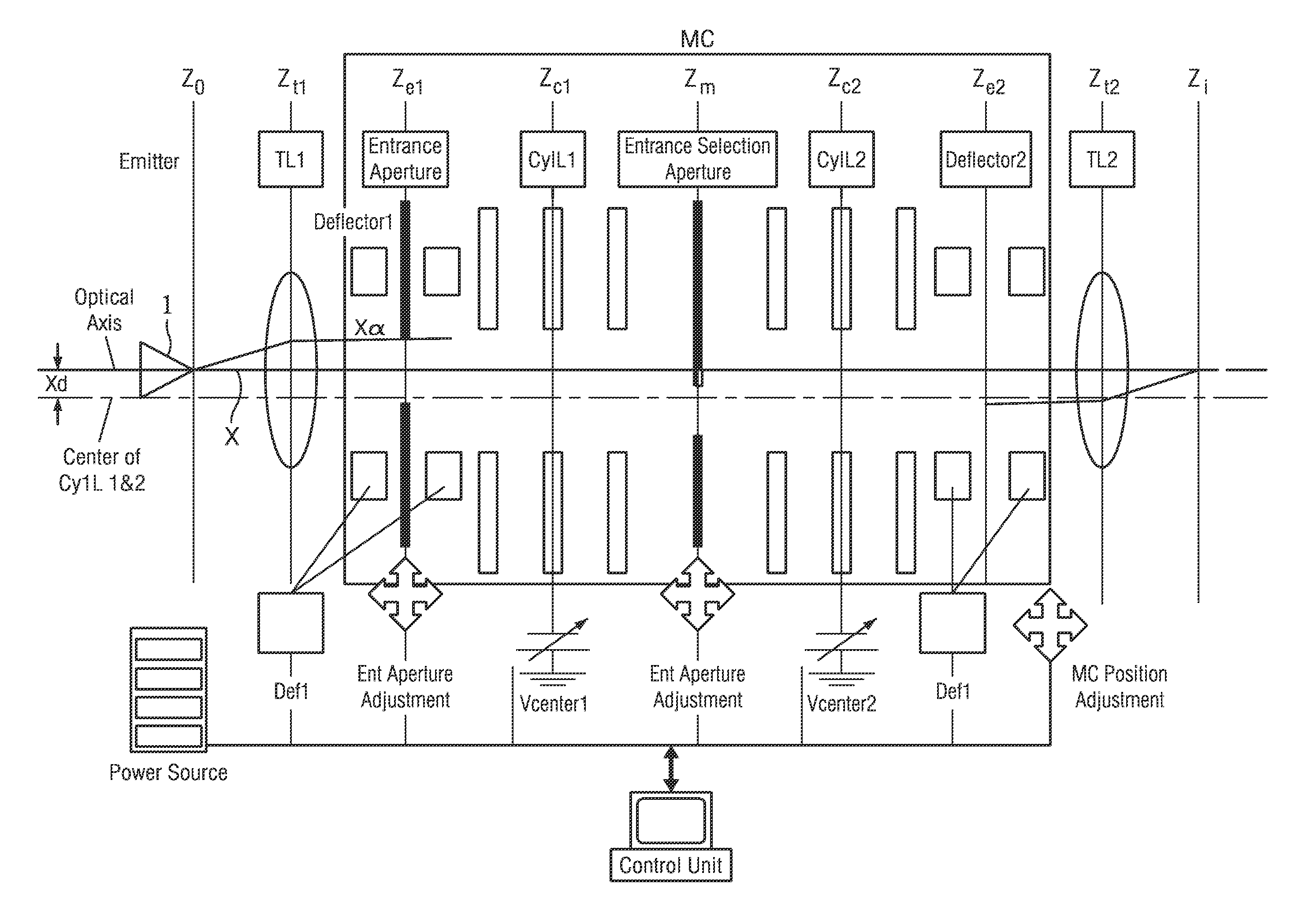
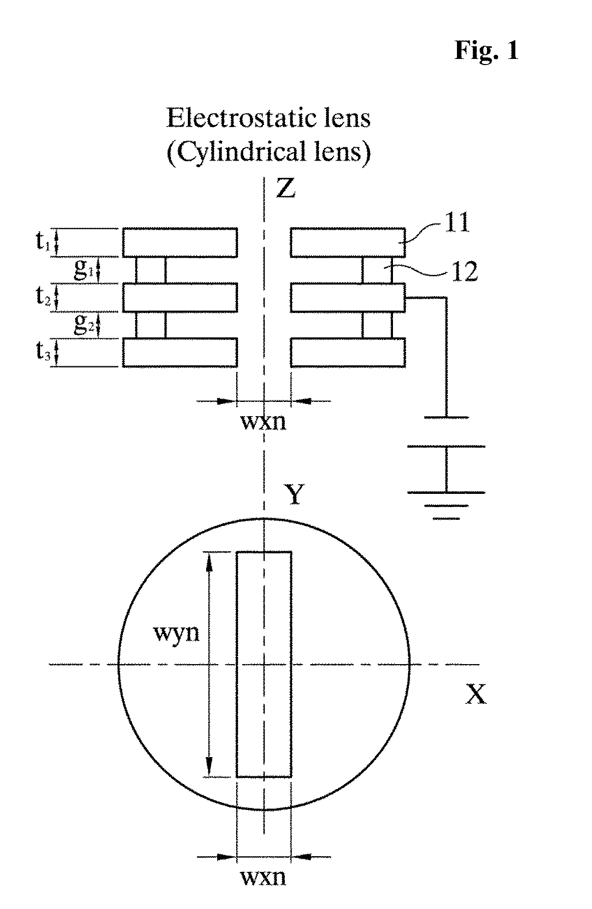
The present invention provides a monochromator that can produce an excellent profile of a charged particle beam even after it passes through the monochromator. By using a two-stage cylindrical lens and a slit to select energy, the monochromator does not have any secondary aberration and primary energy dispersion. This allows a charged particle beam in the central part of the emitter to be used.

Problems solved by technology

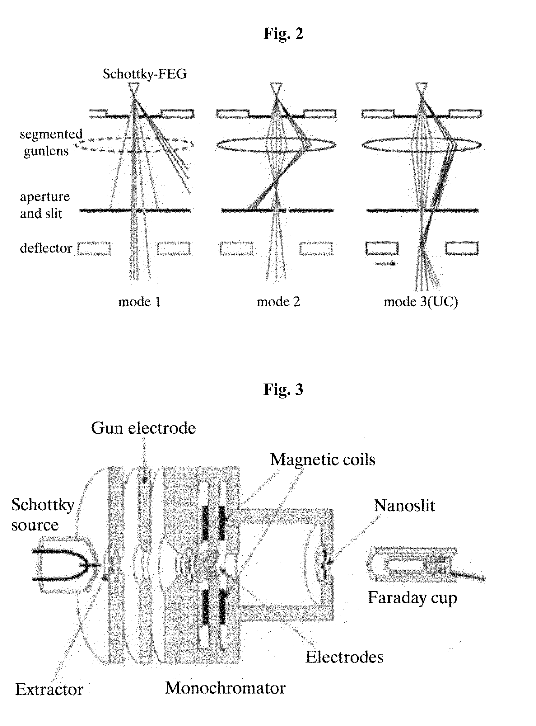
However, the aforementioned conventional monochromators are problematic in that they are complicated in structures and very expensive and they require a high level of precision in fabrication and a large number of power sources.
In particular, the monochromator MC of FEI Co., Ltd. illustrated in FIG. 4 has the simplest structure, but is problematic in that an off-axis aberration, such as coma and astigmatism, remains in order for a charged particle beam to pass through the outside of the axis of a lens and the profile of the charged particle beam is adversely affected at the back.
Furthermore, there is a problem in that energy spread of the original electron beam is increased and an emission current becomes unstable if a component in the axis of an electron source is to be used.

Method used


Image

  • Monochromator and charged particle apparatus including the same
  • Monochromator and charged particle apparatus including the same
  • Monochromator and charged particle apparatus including the same

Examples


embodiment 6

[0074]In another embodiment of the present invention, two twelve poles each formed of an electrode or magnetic pole symmetrically divided into twelve parts may be disposed in series at each of the locations of the first multipole 1 and the second multipole 2. The twelve poles may be formed by overlapping the aforementioned quadrupole, hexapole, and octapole with each other. In accordance with another embodiment of the present invention, the twelve poles can correct respective aberrations occurring in the cylindrical lens at the energy selection location Zm. In accordance with another embodiment of the present invention, optics capable of obtaining a high current in the same energy resolution can be realized because the diameter of a charged particle beam is identically maintained in a condition in which a higher current is obtained. Alternatively, energy resolution in the same amount of current can be improved because the diameter of a charged particle beam is reduced in the same cu...

embodiment 1

Another Embodiment 1

[0084]FIG. 20 is a diagram illustrating a charged particle beam apparatus in accordance with another embodiment of the present invention. As illustrated in FIG. 20, optics in which the first transfer lens TL1 and second transfer lens TL2 of the monochromator MC in accordance with an embodiment of the present invention are used as a focusing lens and an object lens are effective in an SEM and FIB that are particularly used in a low acceleration voltage. In accordance with another embodiment 1 of the present invention, the influence of a spatial charge effect can be reduced because optics not having a focus point in a column can be realized. Furthermore, in accordance with another embodiment 1 of the present invention, stiffness can be increased and anti-vibration can be improved because the number of optical elements is reduced and the length of equipment is made small. In this case, the size of the emitter is reduced so that a ratio of the focal distances of the ...

embodiment 2

Another Embodiment 2

[0085]FIG. 21 is a diagram illustrating a charged particle beam apparatus in accordance with another embodiment of the present invention. As illustrated in FIG. 21, if the monochromator MC in accordance with an embodiment of the present invention is integrated with the high voltage part of an electron gun, in particular, it is effective in a charged particle beam apparatus, such as a transmission electron microscope (TEM) and a scanning transmission electron microscope (STEM) having high charged particle beam energy. An acceleration tube 50 may be disposed behind the location Zi and used as a TEM or STEM of 60˜300 keV. In this case, energy of charged particles generated by the monochromator MC is about 3-5 keV determined at the extraction voltage of the emitter, and an acceleration voltage applied by the acceleration tube 50 in the rear stage is accelerated with 100˜300 keV. Energy resolution in the monochromator MC is constant because energy of the monochromator...


PUM


Abstract

Disclosed herein are a monochromator and a charged particle beam apparatus including the same. The monochromator may include a first electrostatic lens configured to have a charged particle beam discharged by an emitter incident on the first electrostatic lens, refract a ray of the charged particle beam, and include a plurality of electrodes and a second electrostatic lens spaced apart from the first electrostatic lens at a specific interval and configured to have a central axis disposed identically with a central axis of the first electrostatic lens, have the charged particle beam output by the first electrostatic lens incident on the second electrostatic lens, refract the ray of the charged particle beam, and comprise a plurality of electrodes. Accordingly, there is an advantage in that a charged particle beam can have an excellent profile even after passing through the monochromator.

Description

CROSS REFERENCE TO RELATED APPLICATION[0001]The present application claims the benefit of Korean Patent Application No. 10-2014-0075947 filed in the Korean Intellectual Property Office on Jun. 20, 2014, the entire contents of which are incorporated herein by reference.BACKGROUND OF THE INVENTION[0002]1. Technical Field[0003]The present invention relates to a monochromator and a charged particle beam apparatus including the same and, more particularly, to a monochromator (MC) for matching optical axes with a low cost and a charged particle beam apparatus including the same.[0004]2. Description of the Related Art[0005]A monochromator is an apparatus for supplying light of a narrow wavelength range and is optics / monochrome spectrometer for extracting desired monochromatic light by performing spectroscopy on white light through a combination of a lens and a slit. Such a monochromator is used optics in a charged particle beam apparatus or used as an energy analyzer. An example of a conve...

Claims


Application Information

Patent Timeline
IPC IPC(8): H01J37/12G01N23/225H01J49/44H01J37/21H01J37/05
CPCH01J37/12H01J37/21H01J37/05G01N23/2251H01J2237/2448H01J2237/1516H01J2237/057H01J2237/24485H01J49/44
Inventor OGAWA, TAKASHICHO, BOK LAEAHN, SANG JUNGPARK, IN YONGHAN, CHEOLSU
Owner KOREA RES INST OF STANDARDS & SCI
Learn More