LED Lighting Device and Packaging Method
- Summary
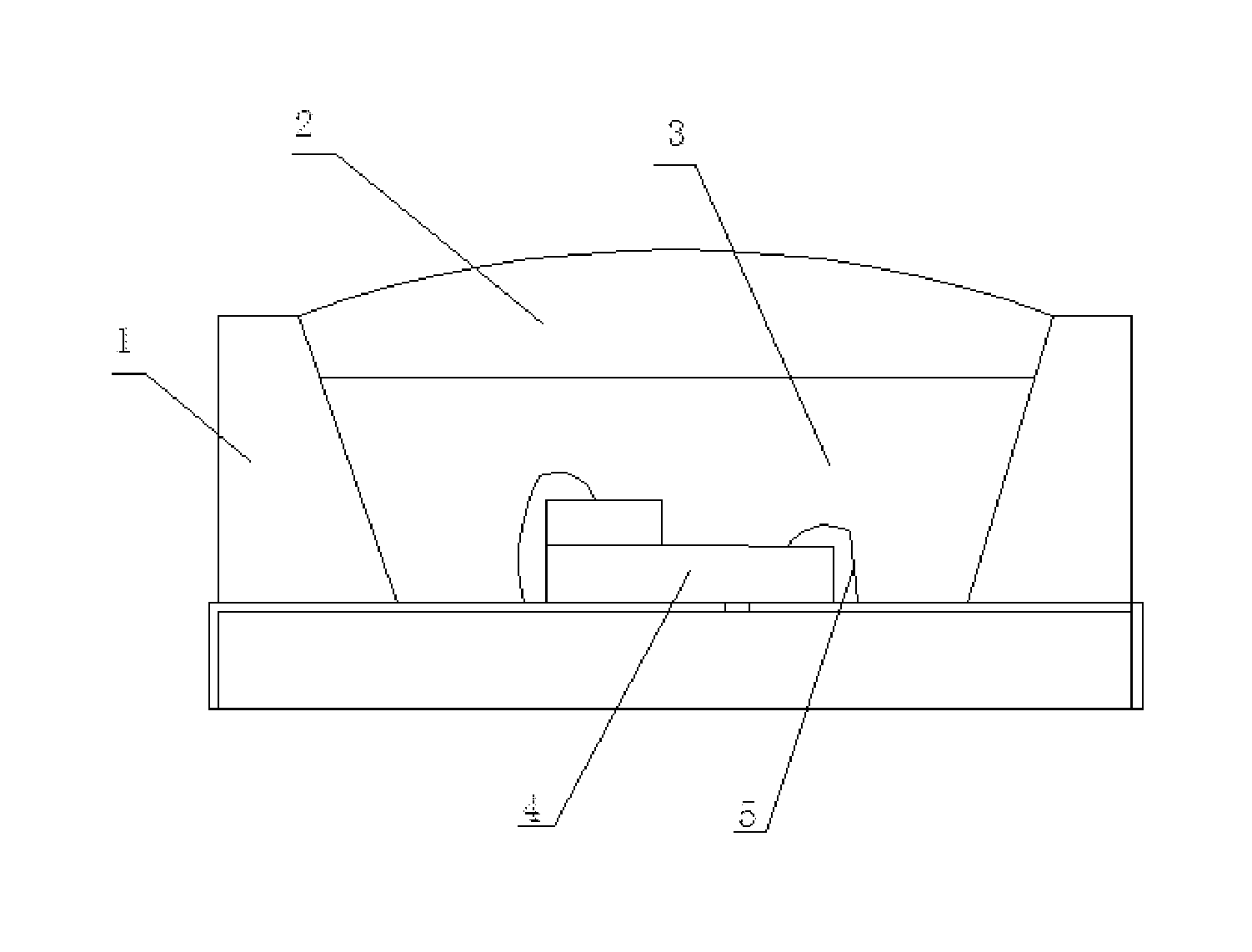
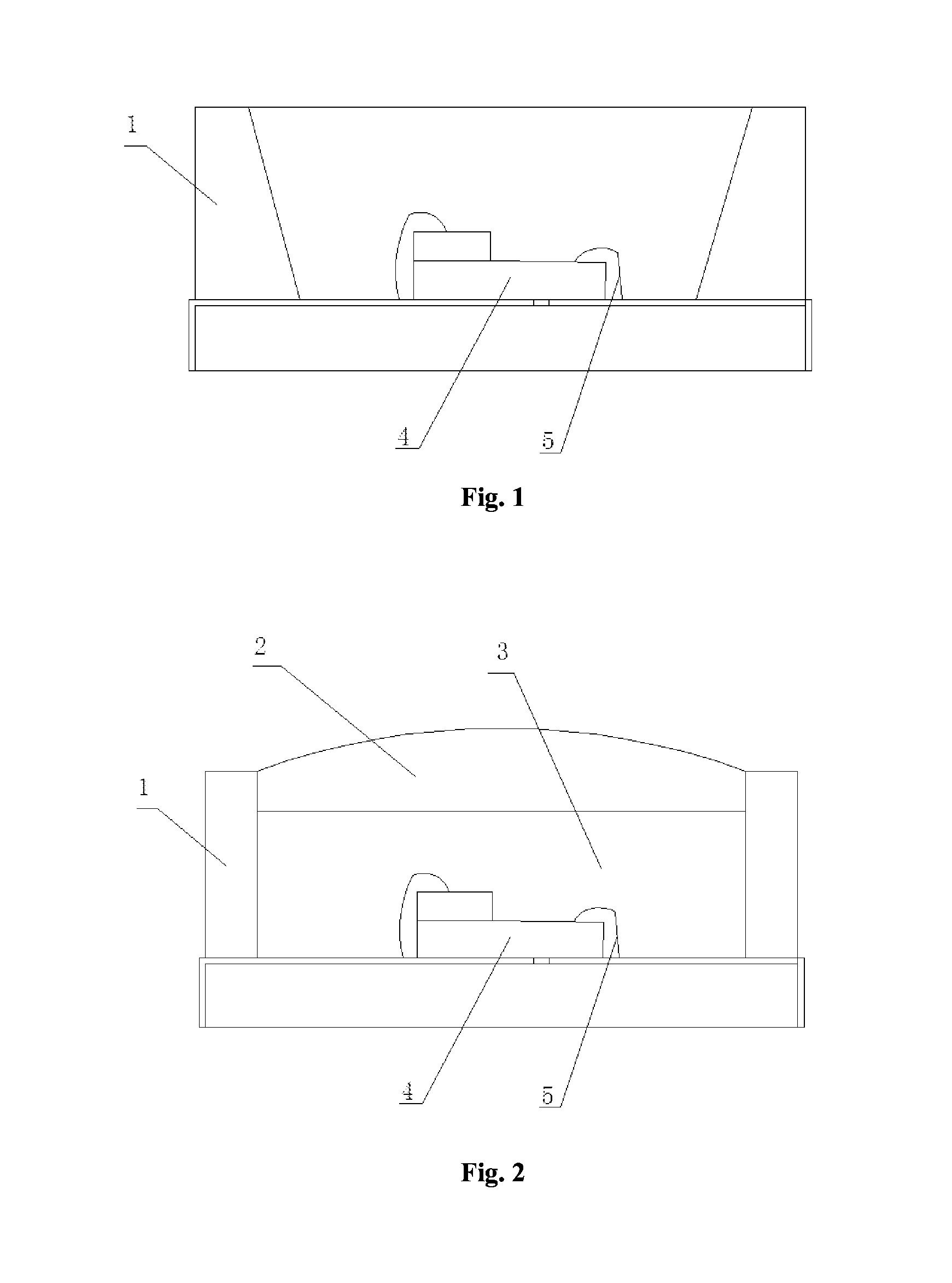
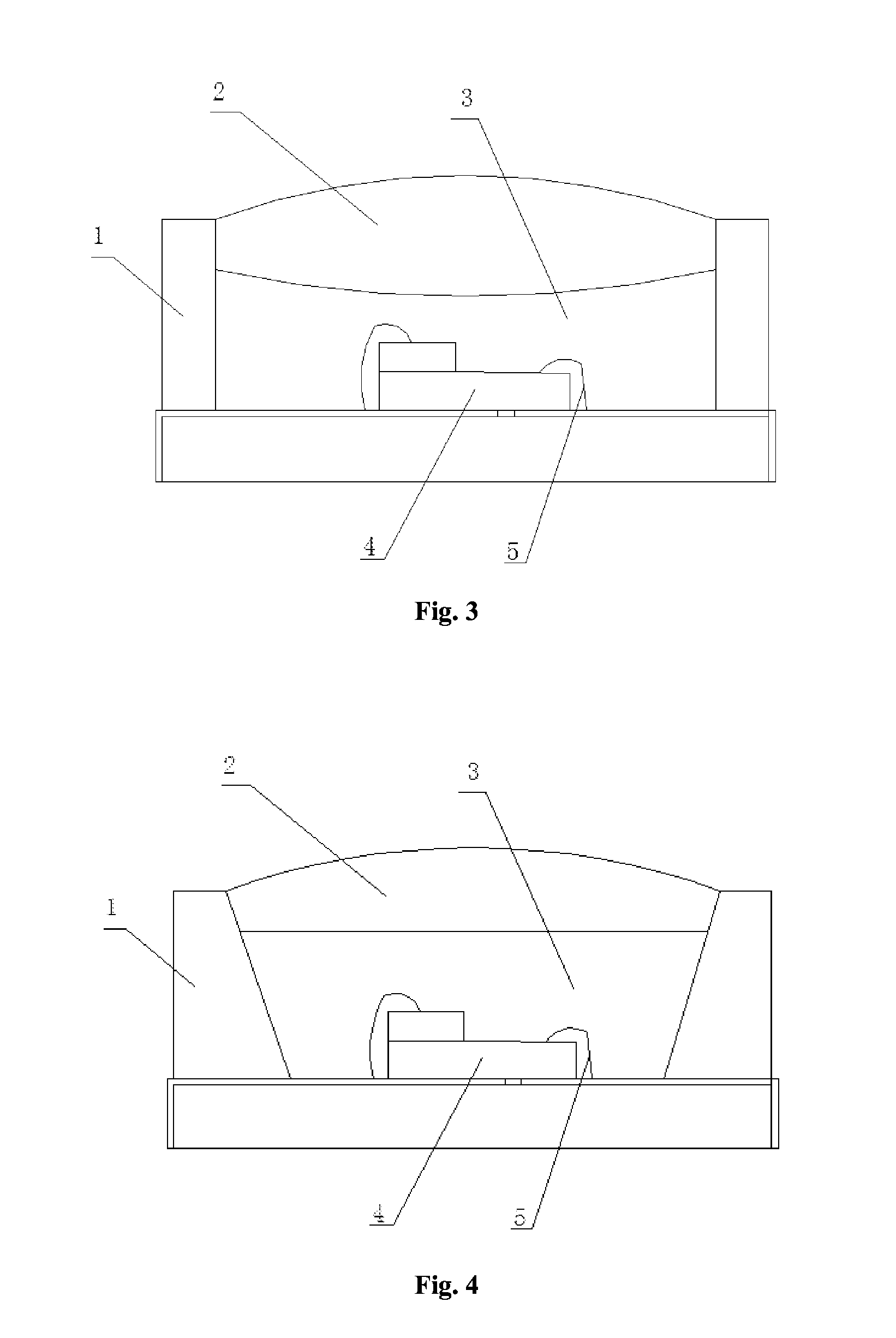
- Abstract
- Description
- Claims
- Application Information
AI Technical Summary
Benefits of technology
Problems solved by technology
Method used
Image

Examples
Embodiment Construction
[0022]The implementations of the disclosure are further described below in detail in conjunction with the accompanying drawings and the embodiments. The following embodiments are used for illustrating the disclosure, rather than limiting the scope of the disclosure.
[0023]In the description of the disclosure, unless otherwise noted, the term ‘a plurality of’ indicates two or more; the orientations or position relationships indicated by the terms ‘up’, ‘down’, ‘left’, ‘right’, ‘inside’, ‘outside’, ‘front end’, ‘rear end’, ‘head’, ‘tail’ and the like are based on the orientations or position relationships shown in the drawings, and these terms are only for convenience of describing the disclosure and simplifying the description, instead of indicating or implying that the device or component must be in a specific orientation, and configured and operated at a specific orientation, and therefore cannot be interpreted as limits on the disclosure.
[0024]In the description of the disclosure, ...
PUM
 Abstract
Description
Claims
Application Information
 - R&D
- Intellectual Property
- Life Sciences
- Materials
- Tech Scout
- Unparalleled Data Quality
- Higher Quality Content
- 60% Fewer Hallucinations
Browse by: Latest US Patents, China's latest patents, Technical Efficacy Thesaurus, Application Domain, Technology Topic, Popular Technical Reports.
© 2025 PatSnap. All rights reserved.Legal|Privacy policy|Modern Slavery Act Transparency Statement|Sitemap|About US| Contact US: help@patsnap.com