Method and apparatus for manufacturing split antenna RFID tag
- Summary
- Abstract
- Description
- Claims
- Application Information
AI Technical Summary
Benefits of technology
Problems solved by technology
Method used
Image
Examples
Embodiment Construction
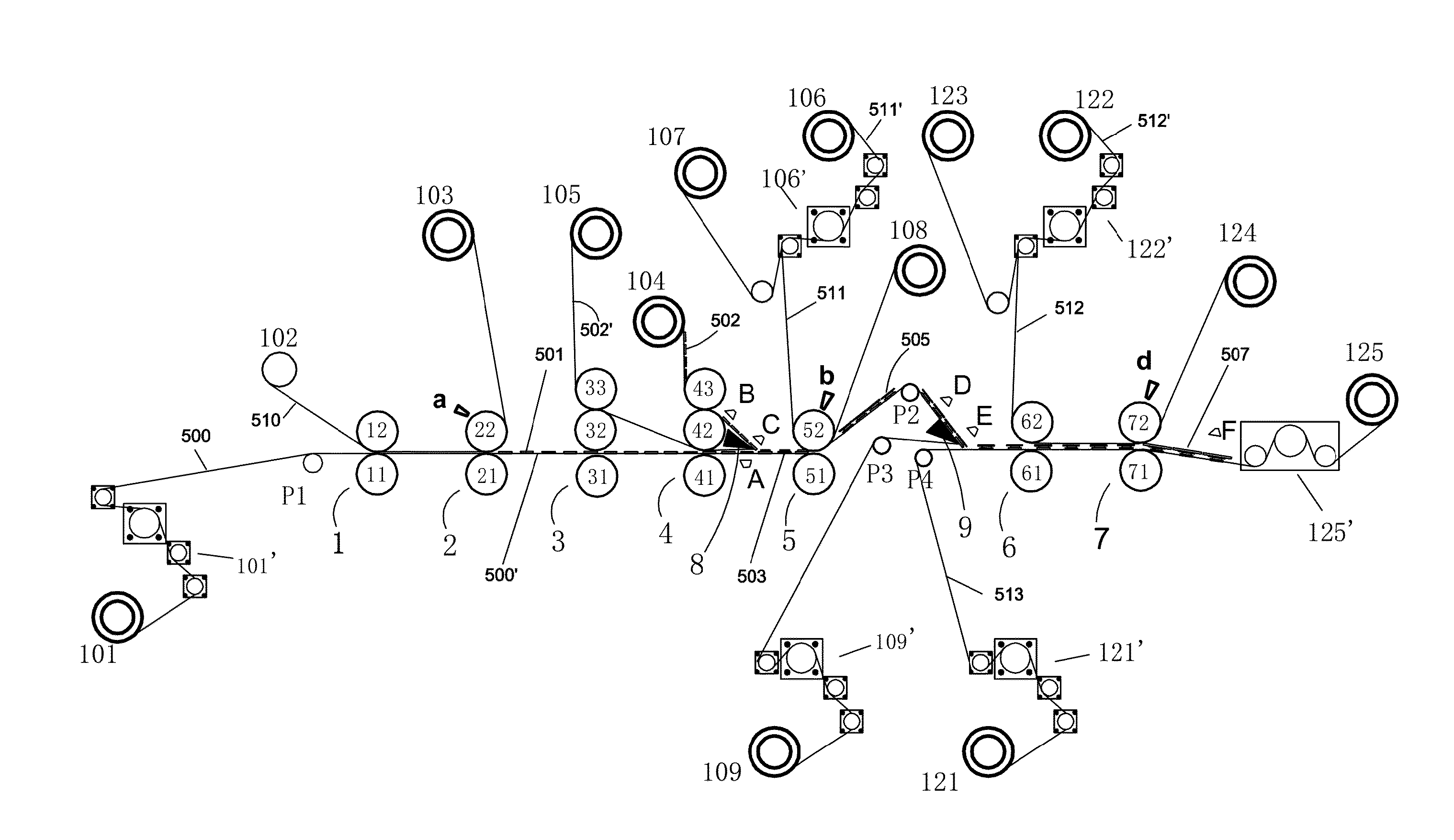
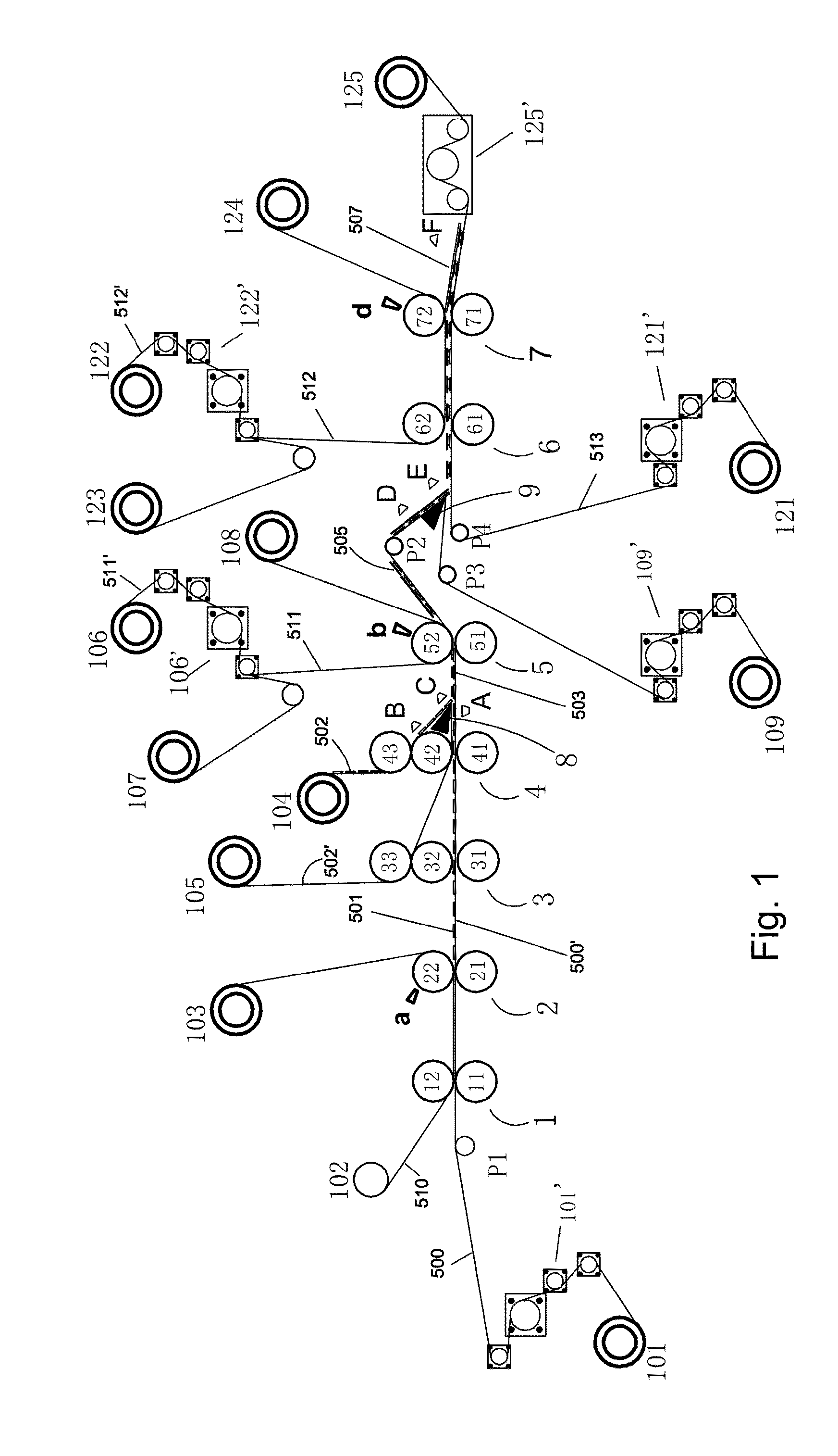
[0039]The present invention will be described below in detail referring to the embodiments of both the split antenna RFID tags and an apparatus.
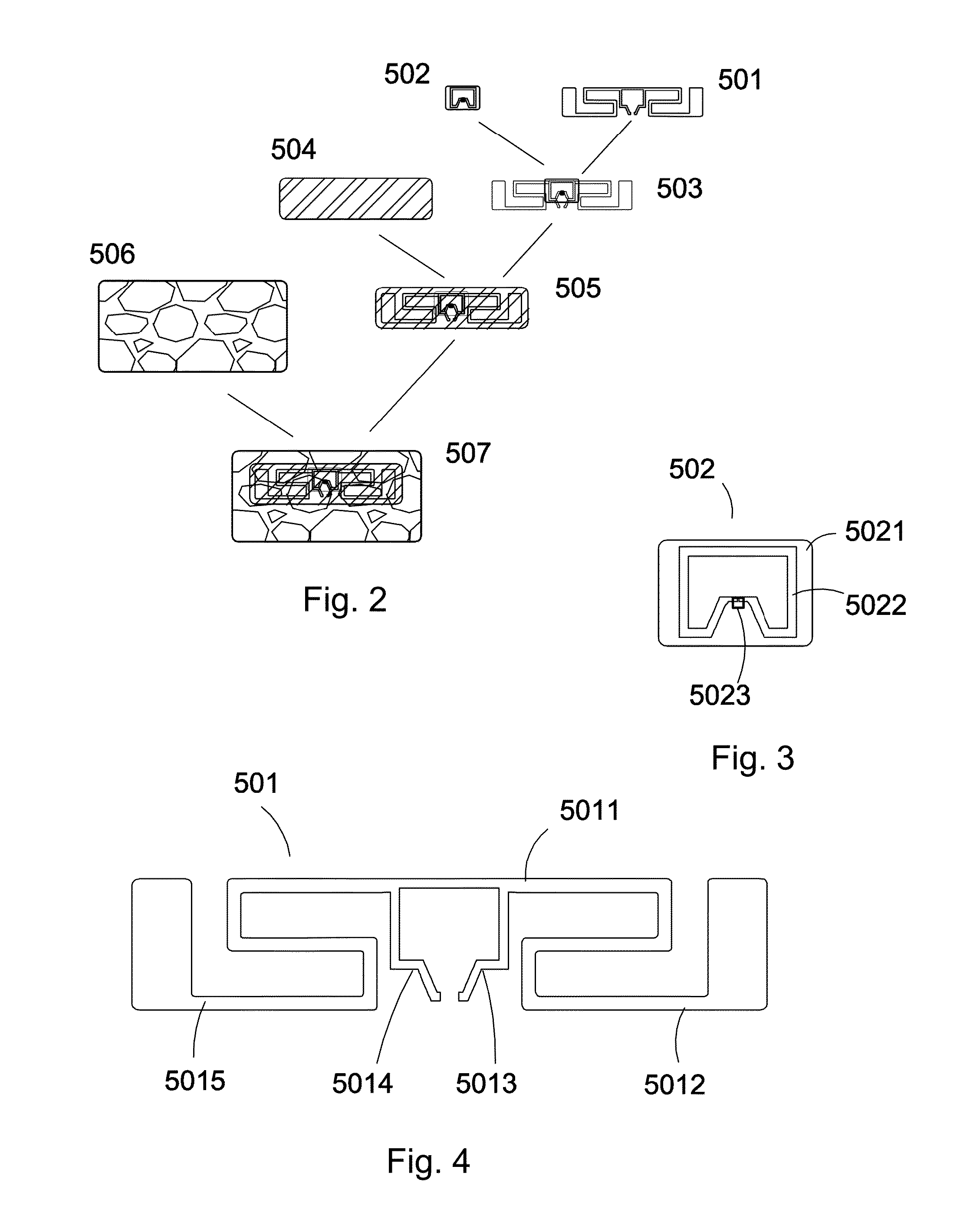
[0040]An embodiment of a split antenna RFID tag in FIG. 2 mainly includes four portions: a die cut aluminum foil antenna 501, an RFID unit 502, a PET film 504 and a surface liner 506, which are successively stacked from bottom to top to form a split antenna RFID tag.
[0041]As shown in FIG. 3, the RFID unit 502 includes a base film 5021, a radiating antenna 5022 printed on the base film and a radio frequency IC 5023. The radiating antenna 5022 is square as a whole and bent at a lower edge thereof inward to form a concave portion with an opening in the middle, and the radio frequency IC 5023 is connected to the opening. The RFID unit 502 may be manufactured by a conventional process. Back glue is adhered to a base tape 502′ at a certain step distance L2, and the base tape 502′ is a release tape such as a release liner tape. The radiating antenn...
PUM
| Property | Measurement | Unit |
|---|---|---|
| Thickness | aaaaa | aaaaa |
| Thickness | aaaaa | aaaaa |
Abstract
Description
Claims
Application Information
 - R&D
- Intellectual Property
- Life Sciences
- Materials
- Tech Scout
- Unparalleled Data Quality
- Higher Quality Content
- 60% Fewer Hallucinations
Browse by: Latest US Patents, China's latest patents, Technical Efficacy Thesaurus, Application Domain, Technology Topic, Popular Technical Reports.
© 2025 PatSnap. All rights reserved.Legal|Privacy policy|Modern Slavery Act Transparency Statement|Sitemap|About US| Contact US: help@patsnap.com


