
Axi-Symmetric Small-Footprint Gyroscope with Interchangeable Whole-Angle and Rate Operation

a gyroscope and small-footprint technology, applied in the field of micro-machined gyroscopes, can solve the problems of reducing the accuracy of the gyroscope, reducing the difficulty of obtaining a high-q factor in a compact volume, and achieving the effect of preventing vibrational motion

Active Publication Date: 2015-12-10
RGT UNIV OF CALIFORNIA
View PDF19 Cites 12 Cited by
  • Summary
  • Abstract
  • Description
  • Claims
  • Application Information

AI Technical Summary

Benefits of technology

This patent describes a new design for a toroidal ring gyroscope that has a strong outer anchor and a distributed suspension system. This design concentrates vibrational energy towards the innermost ring and prevents it from spreading to the outer anchor, resulting in a high Q-factor and a compact size. The gyroscope can be made using standard silicon on insulator processes. Additionally, the patent describes a method for driving the gyroscope using a distributed suspension system and a micro-controller to control its orientation. The invention also provides a method for driving the gyroscope to a predetermined amplitude and stabilizing its phase lock loop and amplitude gain control.

Problems solved by technology

Q-factors as high as 1 million was demonstrated on a quadruple mass gyroscope (QMG), however the device had a 9 mm×9 mm footprint.
Despite these successful implementations of degenerate mode operation, obtaining a high-Q factor in a compact volume remains to be a challenge due to factors such as support losses, thermo-elastic dissipation, and viscous damping.

Method used


Image

  • Axi-Symmetric Small-Footprint Gyroscope with Interchangeable Whole-Angle and Rate Operation
  • Axi-Symmetric Small-Footprint Gyroscope with Interchangeable Whole-Angle and Rate Operation
  • Axi-Symmetric Small-Footprint Gyroscope with Interchangeable Whole-Angle and Rate Operation

Examples


Embodiment Construction

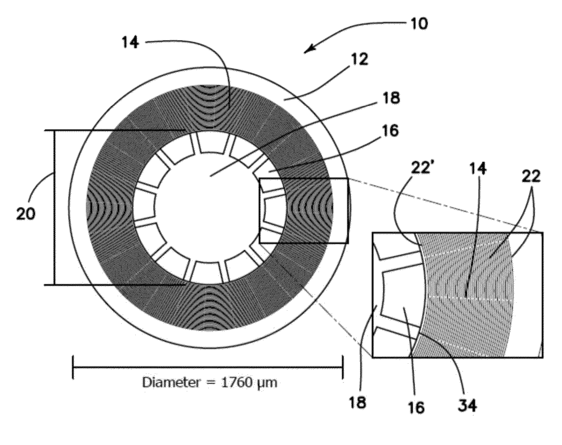
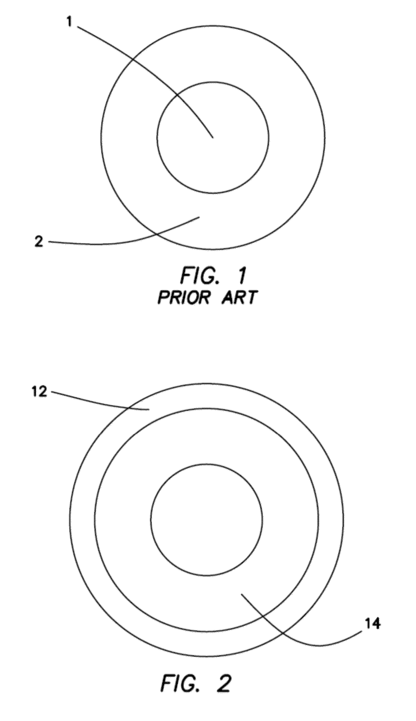
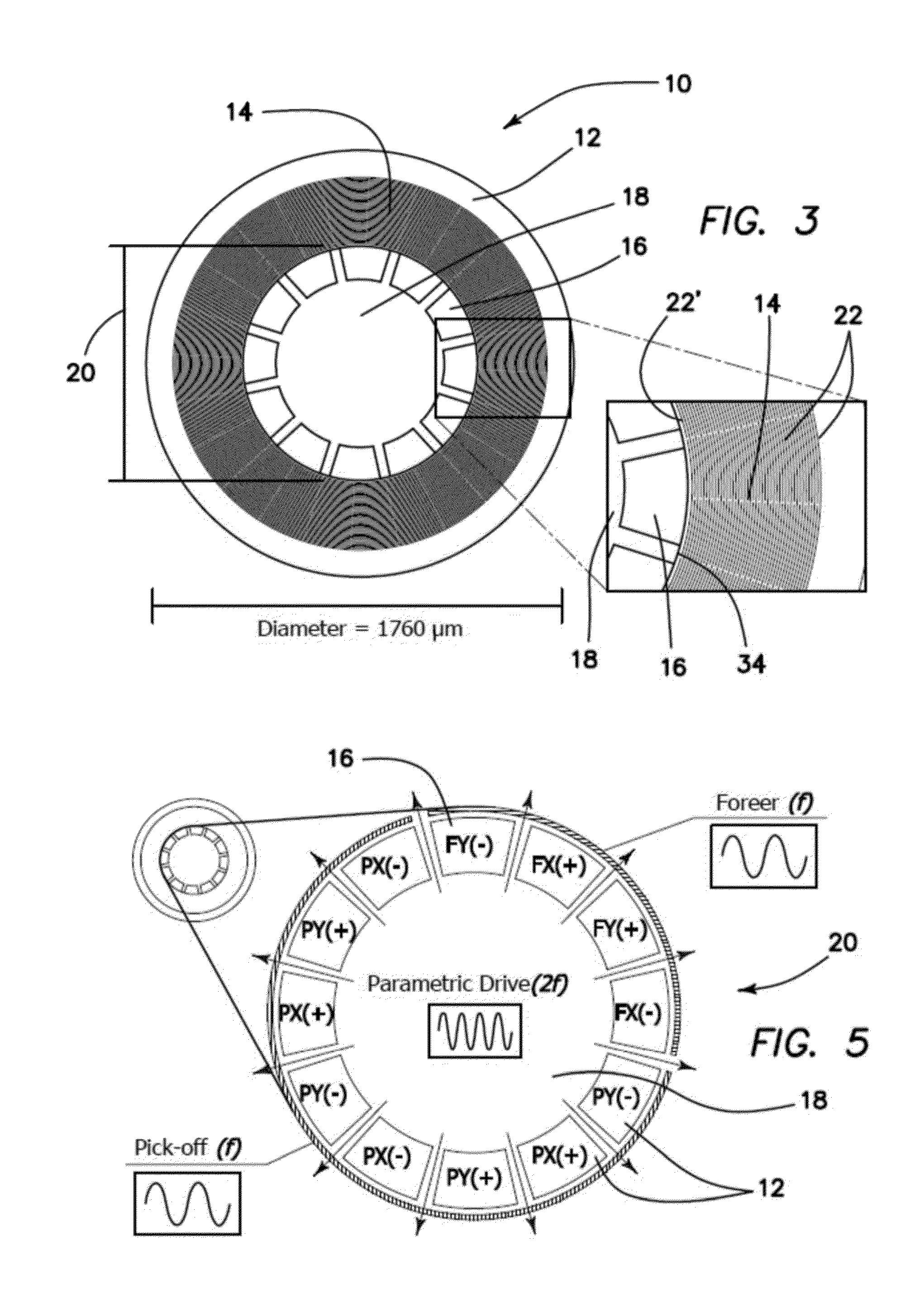
[0048]The current invention is a new type of degenerate mode gyroscope with measured Q-factor of >100,000 on both modes at a compact size of 1760 μm diameter. The toroidal ring gyroscope of the current invention consists of an outer anchor ring, concentric rings nested inside the anchor ring and an electrode assembly at the inner core. Current implementation uses n=3 wineglass mode, which is inherently robust to fabrication asymmetries. Over the 4 devices tested, lowest as fabricated frequency split was found to be 8.5 Hz (122 ppm) with a mean of 21 Hz (Δf / f=300 ppm). Further electrostatic tuning brought the frequency split below 100 mHz (<2 ppm). Whole angle mechanization and pattern angle was demonstrated using a high speed DSP control system. Characterization of the gyro performance using force-rebalance mechanization revealed ARW of 0.047° / √hr and an in-run bias stability of 0.65 deg / hr. Due to the high Q-factor and robust support structure, the device can potentially be instrum...


PUM


Abstract

A toroidal ring gyroscope with a robust outer perimeter anchor and a distributed suspension system. The vibrational energy in the design is concentrated towards the innermost ring, and the device is anchored at the outer perimeter. The distributed support structure prevents vibrational motion propagating to the outer anchor, which helps trap the vibrational energy within the gyroscope and provides a Q-factor of >100,000 at a compact size of 1760 μm. Due to the parametric pumping effect, energy added to each mode is proportional to the existing amplitude of the respective mode. As a result, errors associated with finding the orientation of the standing wave and x-y drive gain drift are bypassed. The toroidal ring gyroscope can be fabricated using any standard silicon on insulator process. Due to the high Q-factor and robust support structure, the device can potentially be instrumented in high-g environments that require high angular rate sensitivity.

Description

RELATED APPLICATIONS[0001]This application is related pursuant to 35 USC 119 to U.S. provisional patent application Ser. No. 62 / 009,764, filed on Jun. 9, 2014, incorporated herein by reference.BACKGROUND[0002]1. Field of the Technology[0003]The current invention relates to micromachined gyroscopes, in particular a toroidal ring gyroscope with a robust ring anchor and a distributed suspension system.[0004]2. Description of the Prior Art[0005]Coriolis Vibratory Gyroscopes (CVGs) can be divided into two broad categories based on the gyroscope's mechanical element: Degenerate mode gyroscopes which have x-y symmetry (Δf=0 Hz ideal) and non-degenerate mode gyroscopes which are designed intentionally to be asymmetric in x and y modes (Δf≠0 Hz). Degenerate mode CVGs have potential advantages over non-degenerate mode CVGs in terms of rate sensitivity, signal to noise ratio, power consumption, and potential to implement whole angle mechanization. However, mechanical elements with high-Q facto...

Claims


Application Information

Patent Timeline
Patent Type & Authority Applications(United States)
IPC IPC(8): G01C19/5684
CPCG01C19/5684
Inventor SENKAL, DORUKSHKEL, ANDREI M.
Owner RGT UNIV OF CALIFORNIA
Learn More