Adiabatic multi-bed catalytic converter with inter-bed cooling

Active Publication Date: 2015-12-10
CASALE SA
View PDF0 Cites 7 Cited by
  • Summary
  • Abstract
  • Description
  • Claims
  • Application Information

AI Technical Summary

Benefits of technology

The invention is a new design for converters used in chemical processes. Its main advantage is that it is simpler and less expensive compared to previous designs. This is because it uses a common heat exchanger for multiple catalytic beds, which eliminates the need for expensive tube sheets. The invention also allows for a more complex design with multiple catalytic beds. A preferred embodiment has four superimposed catalytic beds and a top and bottom inter-bed exchanger for cooling the hot flow. The invention also includes a structurally independent catalytic cartridge that can be used for revamping existing converters. Overall, the invention simplifies the design of converters while keeping the feature of inter-bed cooling, making it more competitive for ammonia converters.

Problems solved by technology

A disadvantage of the known converters is that design and construction become sophisticated and expensive with multiple catalytic beds.
For example, each shell-and-tube heat exchanger needs a respective bundle of tubes with two tube sheets; tube sheets are quite expensive items and weldings between tubes and the tube sheet require careful and expensive execution.
The current prior art considers that a layout with more than three beds and two intermediate exchangers is not convenient.

Method used


Image

  • Adiabatic multi-bed catalytic converter with inter-bed cooling
  • Adiabatic multi-bed catalytic converter with inter-bed cooling
  • Adiabatic multi-bed catalytic converter with inter-bed cooling

Examples


Embodiment Construction

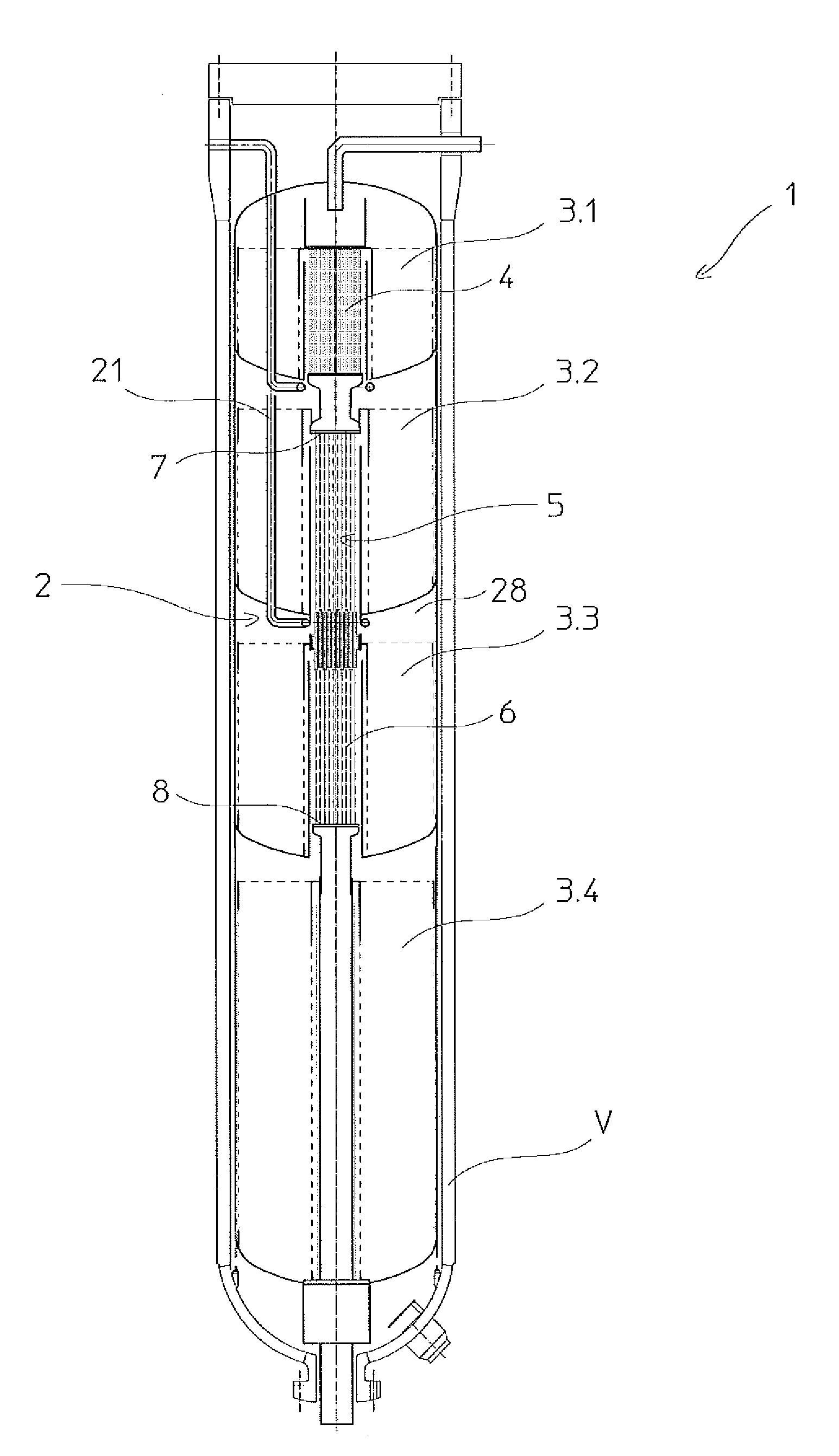
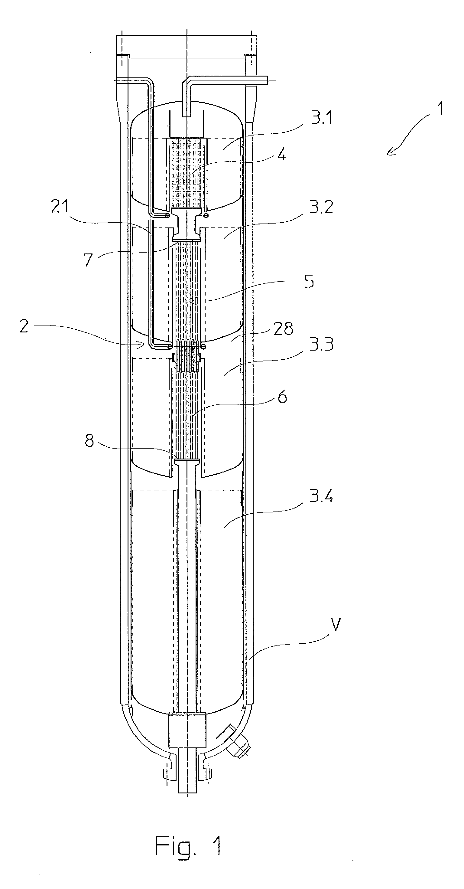
[0027]FIG. 1 discloses a converter 1, for example an ammonia or a methanol converter, comprising a pressure vessel V and a catalytic cartridge 2. Said cartridge 2 is equipped with four catalytic beds denoted with numerals 3.1 to 3.4. The cartridge 2 comprises a suitable basket with side walls and a bottom wall for each catalytic bed, according to known technique which need not be described here. The catalytic beds are arranged in series, that is the effluent leaving a catalytic bed passes to the next catalytic bed for a further step of reaction, possibly after mixing with a quenching gas.

[0028]Each bed is configured with annular cylindrical shape and has a central axial passage; shell-and-tube heat exchangers are arranged in the central passages of at least some of the catalytic beds, to provide inter-bed cooling of the gaseous products evolving from one catalytic bed to another.

[0029]More in detail, referring to FIG. 1 the converter 1 comprises a first heat exchanger 4 arranged ins...


PUM

PropertyMeasurementUnit
Elasticityaaaaaaaaaa

Abstract

A multi-bed catalytic converter (1) with inter-bed heat exchangers, comprising a plurality of superimposed catalytic beds and a common heat exchanger (5) which is shared between two or more consecutive catalytic beds, said common heat exchanger including heat exchange bodies such as a tube bundle (6), and a wall system (9, 10) to define a tube side and a shell side respectively, and the shell side comprising at least a first space (12) and a second space (13), wherein the first space (12) receives the product gas leaving the first of said consecutive beds, and the inter-cooled gas leaving said first space (12) is admitted in the second bed (3-3) for further conversion, and a sealing means (14) preventing a direct gas passage from said first space to said second space.

Description

FIELD OF THE INVENTION[0001]The present invention relates to the field of multi-bed catalytic converters with inter-bed cooling.PRIOR ART[0002]Adiabatic multi-bed catalytic converters are used in several fields, including e.g. the synthesis of methanol and the synthesis of ammonia.[0003]An inter-cooled multi-bed converter comprises a plurality of catalytic beds arranged in series, and one or more inter-bed heat exchangers for cooling the gaseous flow of partially-reacted products (briefly called products) passing from one bed to another.[0004]A common layout can be described as follows. The converter is an elongated vertical pressure vessel hosting a catalytic cartridge; said cartridge includes a plurality of superimposed catalytic beds; each catalytic bed includes an annular cylindrical catalyst container with a central passage, and the inter-bed coolers are usually shell-and-tube heat exchangers fitted in the central passages of said containers. A suitable system of perforated wal...

Claims


Application Information

Patent Timeline
IPC IPC(8): B01J8/04
CPCB01J8/0469B01J8/0496Y10T29/49346B01J2208/00132B01J2208/027B01J8/0415B01J2208/00194B01J2208/00814B01J2219/00024C01C1/0423Y02P20/52
Inventor RIZZI, ENRICOFILIPPI, ERMANNO
Owner CASALE SA
Why Eureka
Try Eureka