
Capacitive sensor configured for using heating element as antenna electrode

Active Publication Date: 2015-12-03
IEE INT ELECTRONICS & ENG SA
View PDF6 Cites 15 Cited by
  • Summary
  • Abstract
  • Description
  • Claims
  • Application Information

AI Technical Summary

Benefits of technology

The patent is about a system that uses a heating element to create a capacitive sensor. The problem with traditional systems is that they have a heating current that leads to steps in the data. This new system solves that problem.

Problems solved by technology

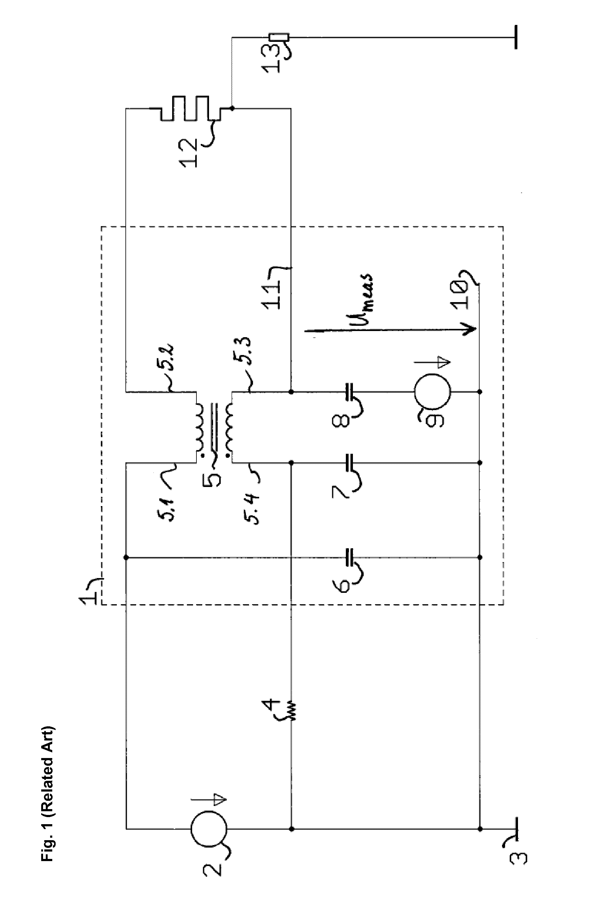
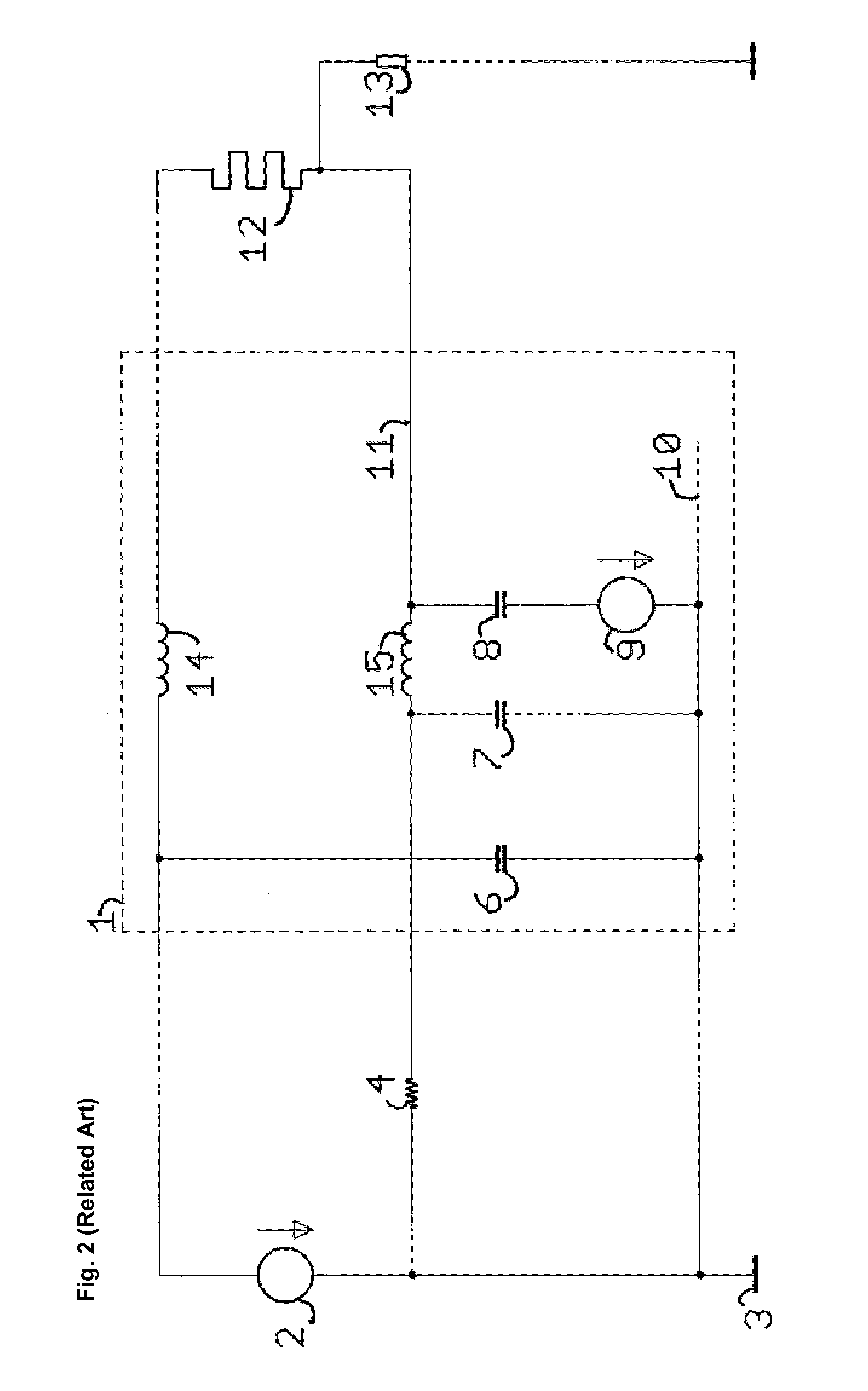
Furthermore, experiments and simulations show that inductors exhibiting the necessary impedance to alternating current below 1 MHz will be so expensive that the solution of U.S. Pat. No. 6,703,845 B2 is unrealistic in an automotive vehicle.

Method used


Image

  • Capacitive sensor configured for using heating element as antenna electrode
  • Capacitive sensor configured for using heating element as antenna electrode
  • Capacitive sensor configured for using heating element as antenna electrode

Examples


second embodiment

[0039]FIG. 5 shows a combined heater and capacitive sensor in accordance with the invention. The capacitive sensor 1 uses basically the same measurement principle as the capacitive sensor of FIG. 3. However, the measurement node (signal input 17.2 of transimpedance amplifier 17) is inductively coupled to the node 11 and thus to the heating element 12 via the third winding of the common mode choke 5. The advantages of the galvanic separation between the measurement node and the heating element are those explained already with respect to FIG. 4.

[0040]The inductive coupling through the third winding of the common mode choke yields an additional advantage. As briefly indicated hereinabove, in an automotive application, an electronic control module is required to be immune against so-called ‘bulk current injection’. The BCI test simulates the influence of electromagnetic fields on the behavior of the electronic control module. A high frequency current is injected into the wiring with a s...

seventh embodiment

[0046]A seventh preferred embodiment of a capacitive sensor according to the invention is shown in FIG. 11. The embodiment of FIG. 11 largely corresponds to the embodiment of FIG. 9 but additionally comprises an amplifier 21 in order to adjust the amplitude of the AC voltage on the shield conductor 22.3. It will thus be appreciated that in the invention the transformer ratio between the third and the first or second winding may be different from one.

[0047]The eighth preferred embodiment of a capacitive sensor according to the invention shown in FIG. 11 combines all the features of the embodiments of FIGS. 10 and 11.

[0048]It is worthwhile noting that in the embodiments of FIGS. 11 and 12, the amplifier 10 could be replaced by an appropriate transformer.

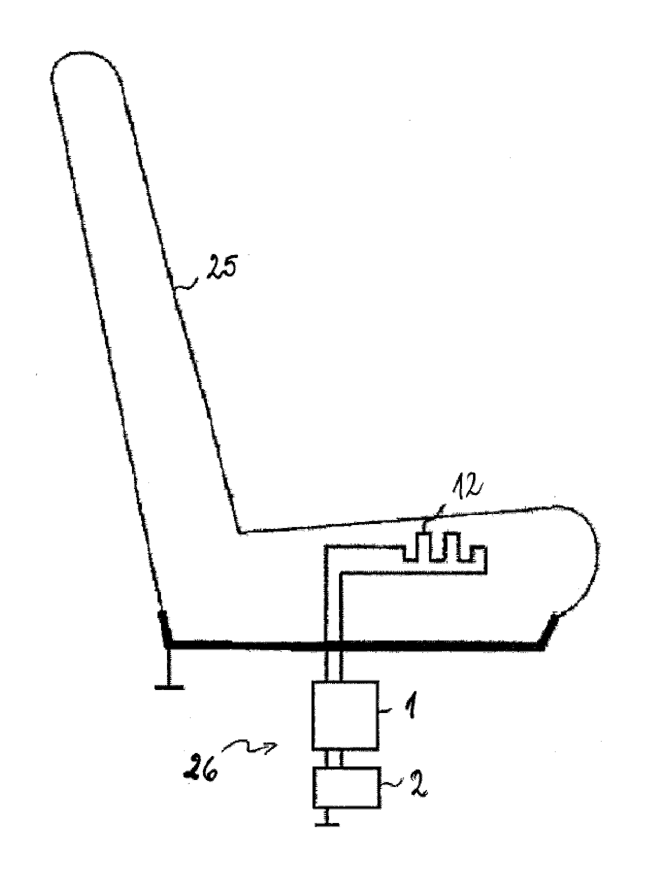
[0049]FIG. 13 shows a vehicle seat 25 equipped with a combined seat heating and capacitive occupant sensing system 26. FIG. 14 shows a steering wheel 28 equipped with a combined heating and capacitive hands-on or hands-off sensing syst...


PUM


Abstract

A capacitive sensor configured for connection between a heating element and a heating current supply comprises a common mode choke (CMC) for AC-decoupling the heating element from the heating current supply. The CMC comprises first and second inductively coupled windings, the first winding for connection between a first terminal of the heating current supply and a first terminal of the heating element and the second winding for connection between a second terminal of the heating element and a second terminal of the heating current supply. The capacitive sensor further comprises a control and evaluation circuit for injecting an AC signal into the heating element via a measurement node, measuring a voltage on and / or a current across the measurement node, and to derive an impedance between the heating element and a counter electrode from the measurement. The CMC comprises a third winding inductively coupled with the first and second windings, the third winding being operatively coupled with the measurement node.

Description

TECHNICAL FIELD[0001]The present invention generally relates to capacitive sensing, e.g. for detecting the presence or absence of a person on a seat (seat occupancy detection) or the presence or absence of a person's hand on the steering wheel of a car (hands-off or hands-on detection.)BACKGROUND ART[0002]Capacitive sensors have a wide range of applications, and are among others used for the detection of the presence and / or the position of conductive body in the vicinity of an antenna electrode. As used herein, the term “capacitive sensor” designates a sensor, which generates a signal responsive to the influence of what is being sensed (a person, a part of a person's body, a pet, an object, etc.) upon an electric field. A capacitive sensor generally comprises at least one antenna electrode, to which is applied an oscillating electric signal and which thereupon emits an electric field into a region of space proximate to the antenna electrode, while the sensor is operating. The sensor...

Claims


Application Information

Patent Timeline
IPC IPC(8): G01D5/24B60H1/00B60R21/015
CPCG01D5/24B60H1/00742B60R21/01552B60N2/5685B60N2/0035B60N2210/12B60N2/002
Inventor LAMESCH, LAURENTVIRNICH, MICHAELPUETZ, MICHAEL
Owner IEE INT ELECTRONICS & ENG SA
Learn More