Compressing device with thermal protection

Inactive Publication Date: 2015-12-03
VALEO AIR MANAGEMENT UK
View PDF11 Cites 9 Cited by
  • Summary
  • Abstract
  • Description
  • Claims
  • Application Information

AI Technical Summary

Benefits of technology

The patent is about a compressor system used in industrial applications. The system includes a first compressor and a second compressor, which can be used downstream of the first compressor. The second compressor has its own drive assembly, which is protected from the output of the first compressor by a seal. This seal prevents damage to the second compressor from the output of the first compressor, and allows the second compressor to be used in various industrial settings. The seal maintains the pressure in the drive assembly independent of the pressure in the compressed air charge. The part of the second compressor that is thermally shielded by the seal is the seal itself. The technical effect of this design is better protection and utilization of the second compressor in industrial applications.

Problems solved by technology

As a result of the desire to reduce carbon dioxide emissions from internal combustion (IC) engines, there is a tendency towards smaller (i.e. reduced capacity) engines.
Whilst the turbocharger may increase the maximum power output of the engine, it has been found to cause unacceptable levels of turbo-lag, often making the engine impractical in automotive applications.
However, in such an arrangement, the downstream compressing device is subjected to especially high temperatures because it receives hot input gases from the upstream compressing device.
This can damage the downstream compressing device and / or restrict the type / design of device that can be used in such an arrangement.

Method used


Image

  • Compressing device with thermal protection
  • Compressing device with thermal protection
  • Compressing device with thermal protection

Examples


first embodiment

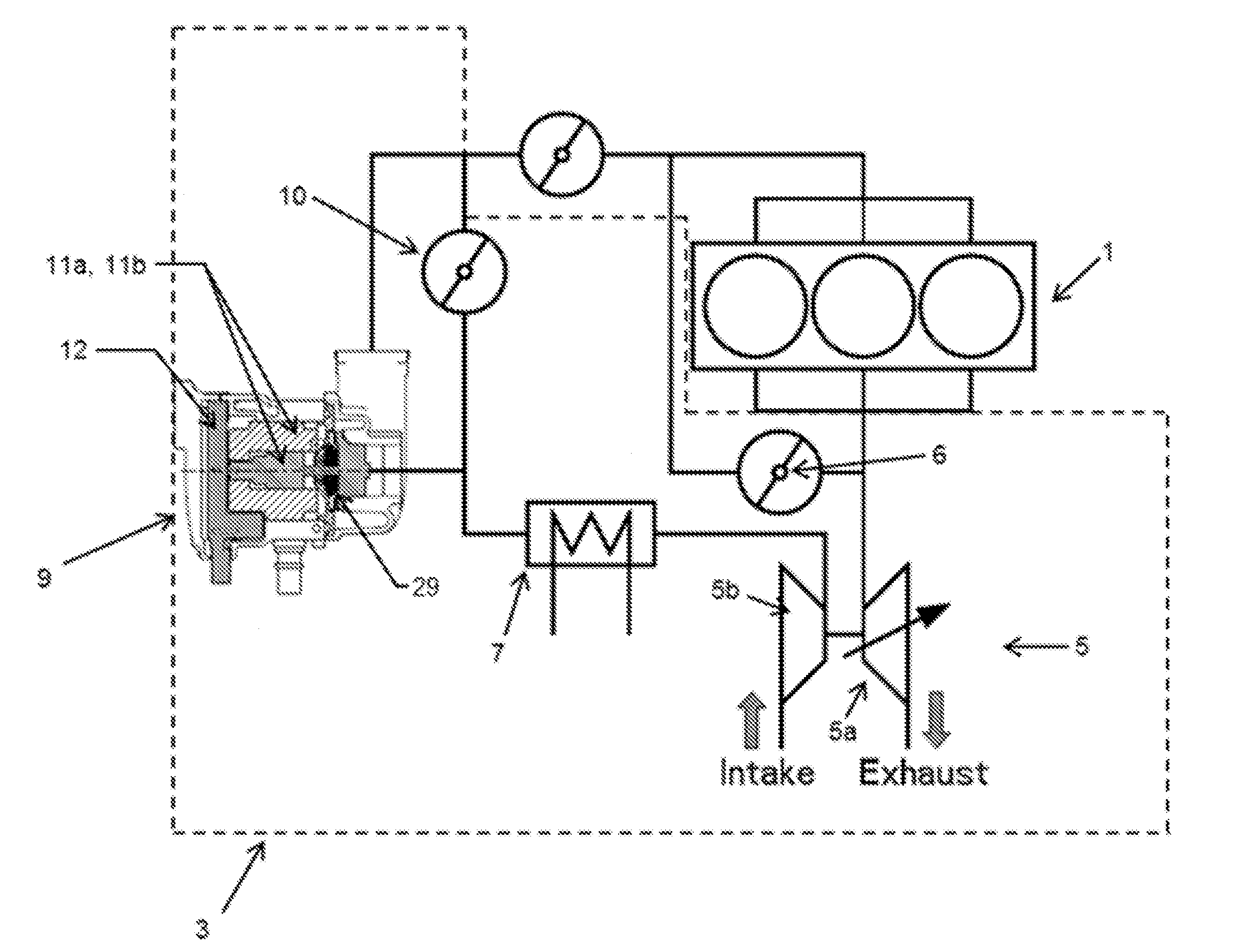
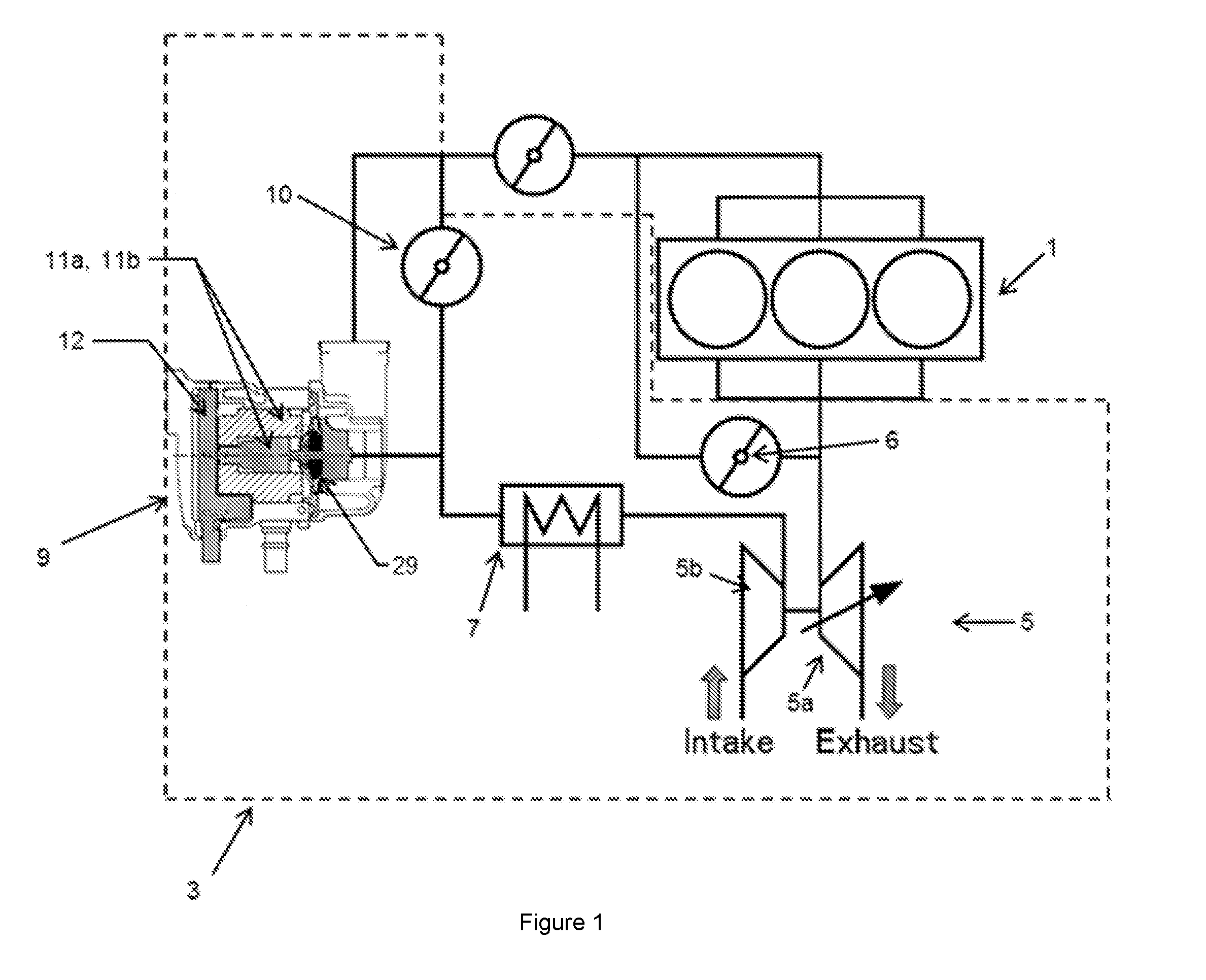
[0021]FIG. 1 shows a three-cylinder internal combustion (IC) engine 1 in combination with an apparatus 3 for supplying compressed intake gases (i.e. a compressed air charge) in accordance with the invention. The apparatus 3 (marked by a dotted line) comprises a turbocharger 5, an exhaust gas recirculation (EGR) valve 6, a charge air cooler (CAC) 7, a supercharger 9 and a supercharger bypass valve 10.

[0022]In accordance with conventional turbochargers, the turbocharger 5 is driven by the exhaust gases from the engine 1 passing through the Variable-Nozzle Turbine (VNT) 5a thereby driving the turbocharger compressor 5b. Some of the exhaust gas output of the engine 1 is returned as an input to the engine via the EGR valve 6.

[0023]The output of the turbocharger 5 is then fed through the CAC 7 before being supplied to the supercharger 9. The supercharger 9 further compresses the output of the turbocharger and supplies the compressed intake gases (referred to herein as a compressed air cha...

second embodiment

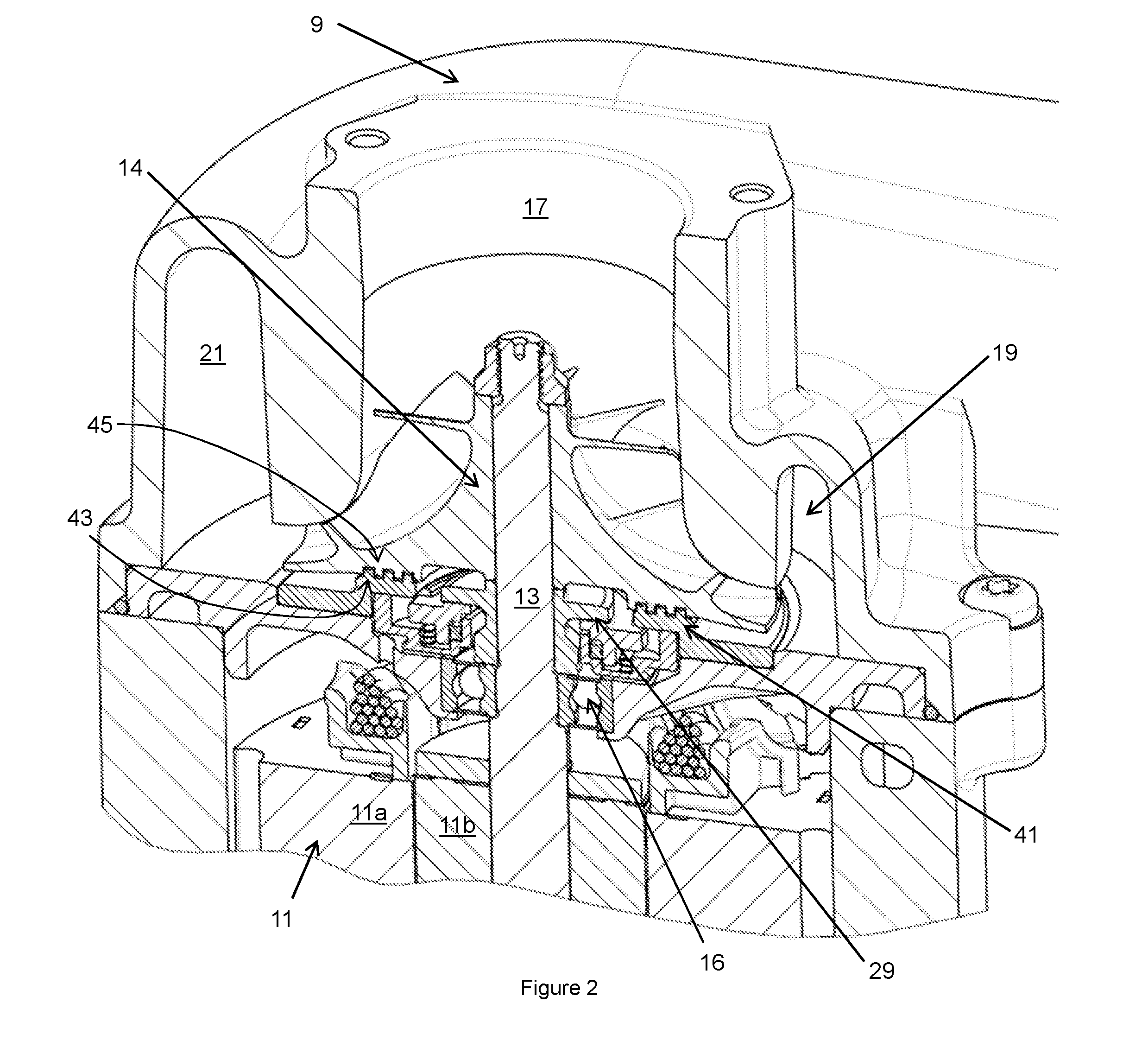
[0032]The supercharger 109 of the second embodiment is part of a similar apparatus to that shown in FIG. 1, except that the intercooler is instead located downstream of the supercharger (and the turbocharger); this means that the compressed charge is especially hot and the thermal shielding afforded by the labyrinth seal is especially important.


PUM


Abstract

An apparatus for supplying an internal combustion engine with a compressed air charge is disclosed. The apparatus includes a first compressing device, for example a turbocharger, and a second compressing device, for example an electric supercharger. The second compressing device is downstream of the first compressing device. A part, for example the bearing assembly, of the second compressing device is thermally shielded from the heat of the compressed air charge by a labyrinth seal.

Description

TECHNICAL FIELD [0001]The present invention relates to compressing devices such as superchargers, and to apparatus comprising two compressing devices for supplying an engine with a compressed air charge.BACKGROUND OF THE INVENTION[0002]As a result of the desire to reduce carbon dioxide emissions from internal combustion (IC) engines, there is a tendency towards smaller (i.e. reduced capacity) engines. In order to maintain acceptable levels of power output, it has been suggested that a turbocharger be fitted to these smaller engines. Whilst the turbocharger may increase the maximum power output of the engine, it has been found to cause unacceptable levels of turbo-lag, often making the engine impractical in automotive applications. Installing a supercharger upstream or downstream of the turbocharger (i.e. between the turbocharger and the engine) has been suggested as a way of reducing this problem of excessive turbo lag. However, in such an arrangement, the downstream compressing dev...

Claims


Application Information

Patent Timeline
IPC IPC(8): F02B37/04F02B33/40
CPCF02B33/40F02B37/04F02B29/0406F02B39/10F04D29/284F04D29/5853F02M26/08Y02T10/12F02B37/004F16J15/4476
Inventor KNIGHT, STEPHEN MICHAEL
Owner VALEO AIR MANAGEMENT UK
Why Eureka
Try Eureka