Ultrasonic probe holder
- Summary
- Abstract
- Description
- Claims
- Application Information
AI Technical Summary
Benefits of technology
Problems solved by technology
Method used
Image


Examples
Embodiment Construction
[0023]Hereinafter, one or more embodiments of the present invention will be described with reference to the drawings. However, the scope of the invention is not limited to the disclosed embodiments.
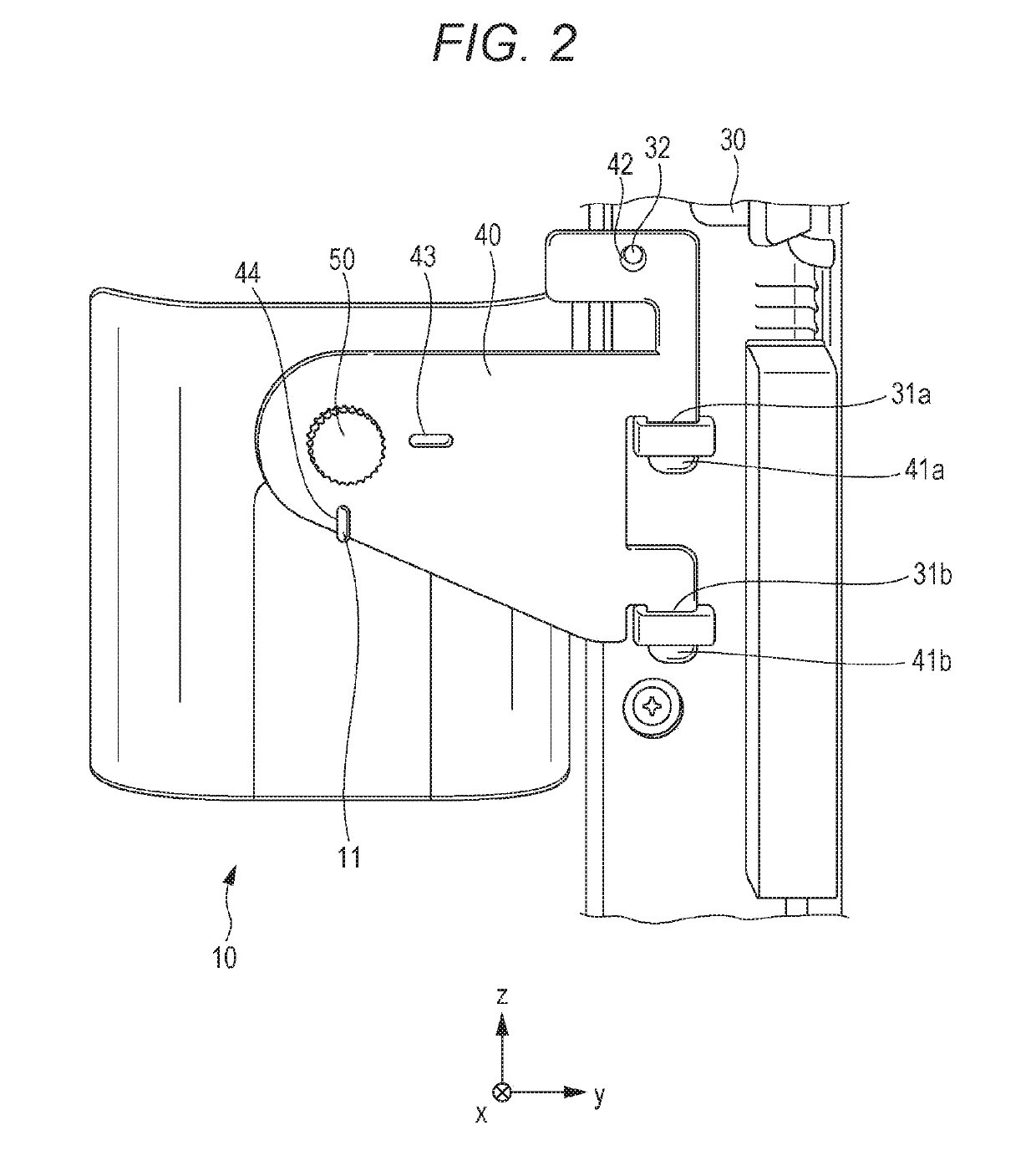
[0024]FIG. 1 is a perspective view illustrating an ultrasonic probe holder 10 according to the embodiment of the present invention. In FIG. 1, an ultrasonic probe 20 and an ultrasonic diagnostic device 30 are also illustrated. Hereinafter, an orthogonal coordinate system of x, y, and z axes illustrated in FIG. 1 is set for the ultrasonic probe holder 10 and the ultrasonic diagnostic device 30. In FIG. 1, the front or a front surface of the ultrasonic probe holder 10 and the ultrasonic diagnostic device 30 are in a +x axis direction, and the back or a back surface of the ultrasonic probe holder 10 and the ultrasonic diagnostic device 30 are in a −x axis direction. Also, an upper side of the ultrasonic probe holder 10 and the ultrasonic diagnostic device 30 is in a +z axis direction, and a ...
PUM
 Abstract
Description
Claims
Application Information
 - R&D
- Intellectual Property
- Life Sciences
- Materials
- Tech Scout
- Unparalleled Data Quality
- Higher Quality Content
- 60% Fewer Hallucinations
Browse by: Latest US Patents, China's latest patents, Technical Efficacy Thesaurus, Application Domain, Technology Topic, Popular Technical Reports.
© 2025 PatSnap. All rights reserved.Legal|Privacy policy|Modern Slavery Act Transparency Statement|Sitemap|About US| Contact US: help@patsnap.com