Steering Wheel Unit

a steering wheel and unit technology, applied in the direction of vehicle components, pedestrian/occupant safety arrangements, vehicular safety arrangments, etc., can solve the problems of noise generation and corresponding wear and tear, and achieve the effect of reducing both noise and wear and tear

Active Publication Date: 2015-11-26
AUTOLIV DEV AB
View PDF3 Cites 5 Cited by
  • Summary
  • Abstract
  • Description
  • Claims
  • Application Information

AI Technical Summary

Benefits of technology

[0005]Proceeding from the previously expressed facts, the object of this invention is to

Problems solved by technology

This results, on the one hand, in noise generation, and on the other hand in the corresponding wear and tear

Method used


Image

  • Steering Wheel Unit
  • Steering Wheel Unit
  • Steering Wheel Unit

Examples


first embodiment

[0039]For a better understanding of the invention the prior art will again be addressed with reference to FIGS. 9 to 19, as it is described in WO 2009 / 149776 A1. As will be seen, the basic design of the invention is very similar to the prior art, so that in the description of the invention reference is accordingly made to the prior art:

[0040]The underlying prior art is now described in more detail using the schematic depictions of FIGS. 9 to 11, as well as on the basis of a concrete embodiment. The basic principle is now described referencing FIGS. 9 to 11.

[0041]FIG. 9 schematically shows a longitudinal cut through the hub area of a steering wheel unit. This steering wheel unit has a steering wheel with a steering wheel body 10, which has a receptacle 12 in the hub area. Spokes 14 extend from the hub area. The steering column 16 extends centrally from the hub area. The direction of extension of the steering column 16 defines the axial direction or Z-direction in the following descri...

second embodiment

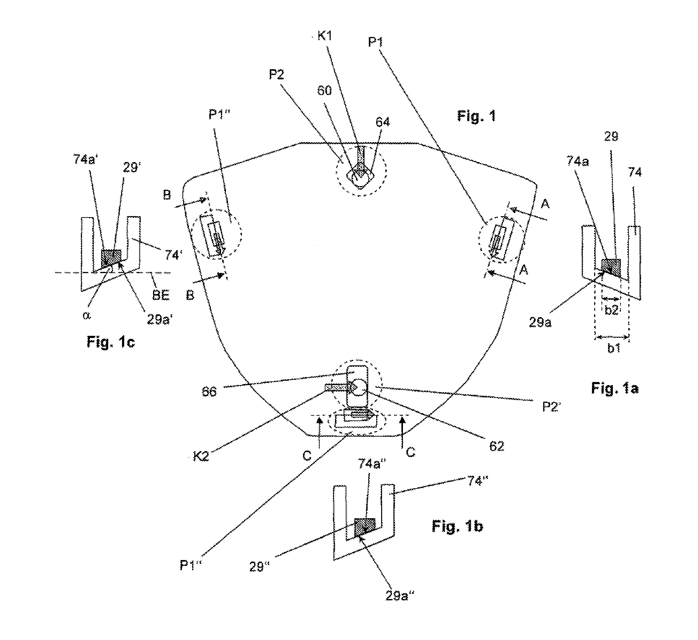
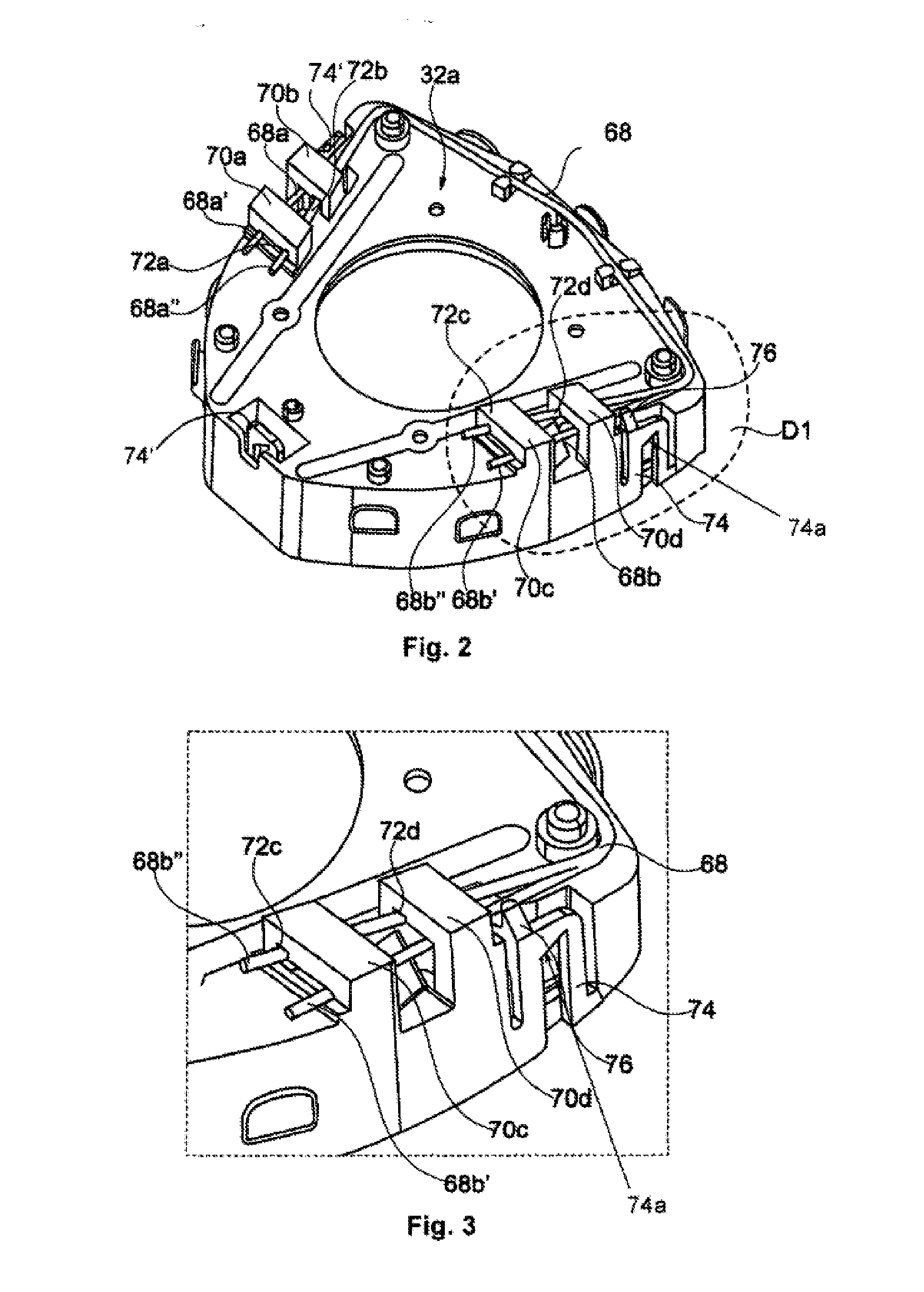
[0064]FIGS. 6 to 8 show the previously described second design. Here the module side positioning elements are part of a ring 120 which encloses an essentially one-piece air bag module as described, for example, in DE 10 2010 006 358 A1. The manner of functioning of the first positioning units is identical to that just described, in particular the U-bolts 74, 74′, and 74″ (which one could also designate as brackets here) can elastically deform, for example, in the radial direction for the purpose of assembly or disassembly. Here, too, the U-bolts 74, 74′ and 74″ (module side positioning elements) and the axial positioning hooks 29 (steering wheel side positioning elements) touch solely across the positioning surfaces and the positioning mating surfaces. In particular the module-side positioning elements and the steering wheel side positioning elements do not touch in the intermediate area between the two positioning surfaces.

[0065]In contrast to the other embodiments depicted, the fi...


PUM


Abstract

A steering wheel unit with a steering wheel body and an air bag module arranged on the steering wheel body and can be depressed on the steering wheel body in an axial direction. Positioning units position the air bag module on the steering wheel, including a first positioning unit (P1, P1′, and P1″), a steering wheel side positioning element with at least one rigid level positioning surface (29a, 29a′, 29a″), and an air bag module side positioning element with at least one rigid positioning mating surface (74a, 74a′, 74a″). The positioning surface and the positioning mating surface are parallel to and abut one another when the air bag module is not depressed. The positioning surface (29a, 29a′, and 29a″) and the positioning mating surface (74a, 74a′, and 74a″) are angled toward one another with respect to a reference plane (BE) which is perpendicular to the axial direction.

Description

CROSS REFERENCE TO RELATED APPLICATIONS[0001]This application claims priority to German Patent Application No. 10 2011 118 090.0, filed Nov. 10, 2011; and PCT / EP2012 / 004624, filed Nov. 7, 2012.TECHNICAL FIELD OF INVENTION[0002]The invention relates to a steering wheel unit for motor vehicle applications with positioning units for an airbag module mounted on the steering wheel body.BACKGROUND[0003]In the generic WO 2009 / 149776 A1 several variants of a steering wheel unit are described with a steering wheel body and an air bag module accommodated in the hub area of the steering wheel body. Several concepts were proposed for positioning the air bag module in the steering wheel body, which all have in common that the axial positioning is effected by means of several positioning units (first positioning units), wherein each positioning unit has a positioning element on the steering wheel side with a rigid, level positioning surface and a positioning element on the airbag module side with...

Claims


Application Information

Patent Timeline
IPC IPC(8): B60R21/203B60R21/217
CPCB60R21/2037B60R2021/2175B60R21/217
Inventor NEBEL, RAIMUND
Owner AUTOLIV DEV AB
Why Eureka
Try Eureka