Wind direction adjuster
a wind direction and adjuster technology, applied in vehicle components, vehicle heating/cooling devices, transportation and packaging, etc., can solve the problems of large actuation space, reduced degree of design freedom, and inconvenient assembly operation performance, etc., to reduce the coupling structure of the operation unit, reduce manufacturing costs, and reduce the effect of the coupling structur
- Summary
- Abstract
- Description
- Claims
- Application Information
AI Technical Summary
Benefits of technology
Problems solved by technology
Method used
Image

Examples
first embodiment
[0059]Hereinafter, a description will be given of a wind direction adjuster according to a first embodiment of the present invention with reference to the accompanying drawings.
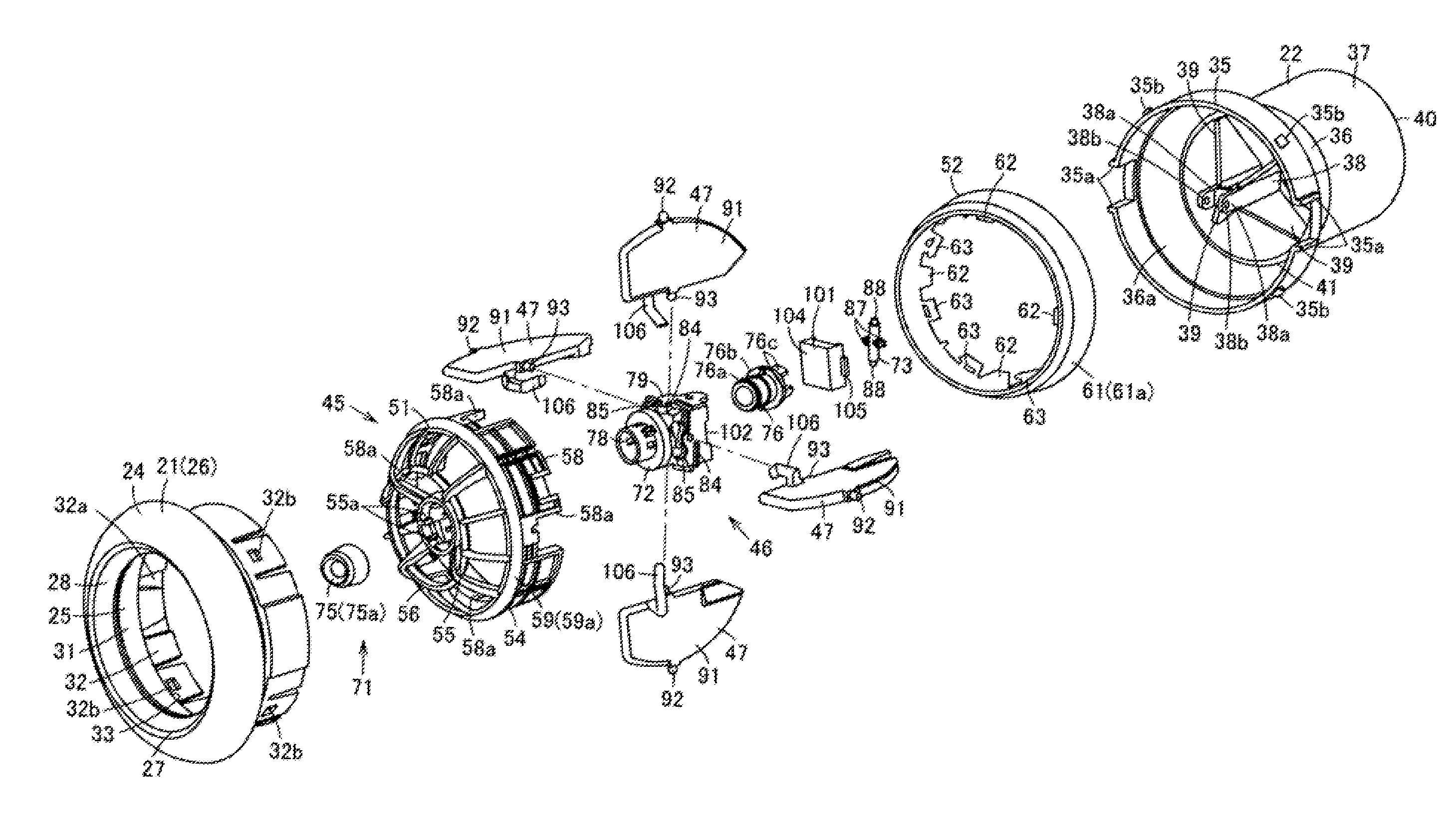
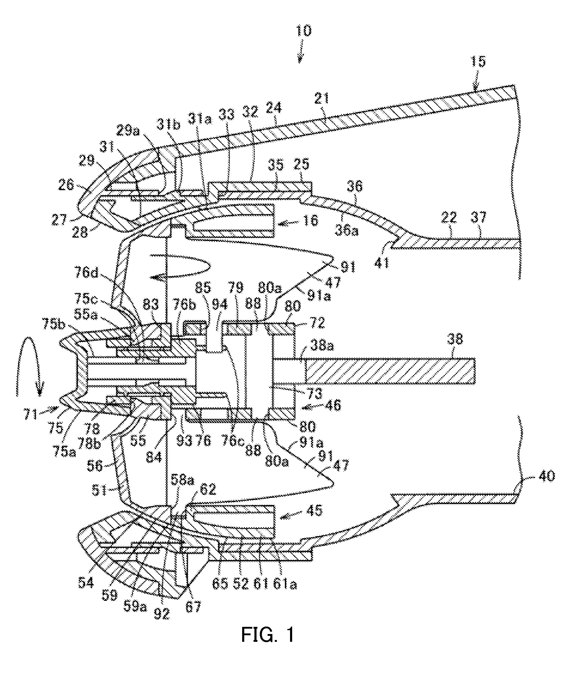
[0060]In FIG. 7, reference numeral 10 denotes a wind direction adjuster. Wind direction adjuster 10 is also called a louver unit or a ventilator, for example. Wind direction adjuster 10 is attached to an instrument panel serving as a component of an automobile for attaching components and is connected to an air conditioner. More specifically, wind direction adjuster 10 is a part of a vehicle air conditioner that blows air into the vehicle interior and performs air conditioning. Hereinafter, a downstream side of blowing wind (leeward side), i.e., the passenger side is referred to as “front side” and an upstream side of wind (windward side) is referred to as “rear side.” In addition, as to the left and right direction and up and down direction, a description will be given, assuming a state where the wind direct...
second embodiment
[0117]Next, a description will be given of a second embodiment with reference to FIGS. 8 through 15. Note that, the components and effects identical to those of the first embodiment are assigned the same reference numerals and the description of these components and effects will not be repeated.
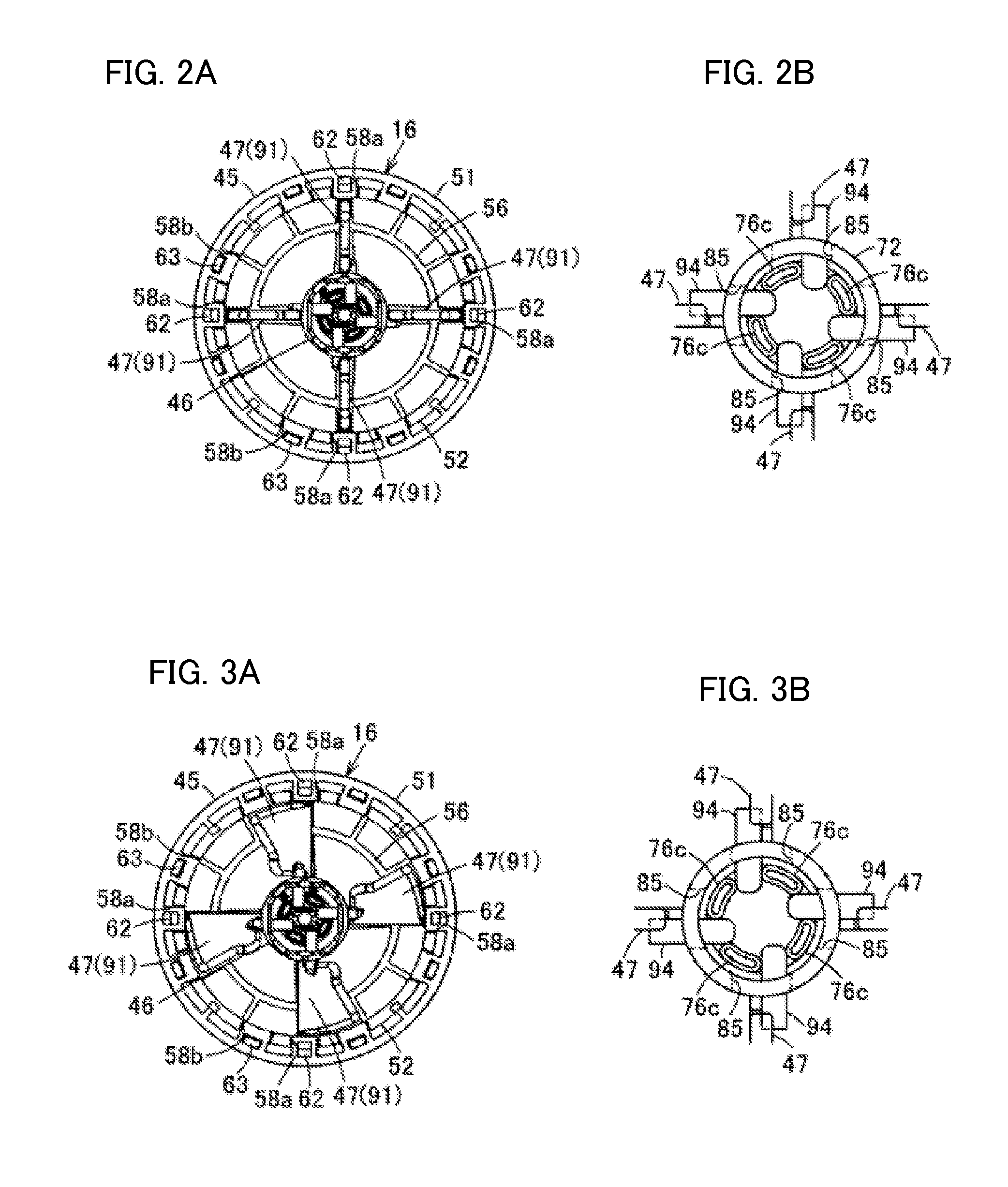
[0118]In the second embodiment, spacer main body 79 of spacer 72 according to the first embodiment is formed in a square tube shape. Long-hole shaped operation openings 85 are formed along with the circumferential direction of spacer 72 so as to curve concentrically with inner-side axial support holes 84 at front side positions that are leeward side positions of inner-side axial support holes 84 formed in the respective surfaces of spacer main body 79. Bearing portions 102 for attaching cover 101, which serves as a blow-by protection body configured to protect wind from blowing out of spacer 72, are made by forming notches at the left and right sides of the rear end portion of spacer main bod...
third embodiment
[0137]Next, a description will be given of a third embodiment with reference to FIGS. 16 through 23. Note that, the components and effects identical to those of the first or the second embodiment are assigned the same reference numerals and the description of these components and effects will not be repeated.
[0138]In the third embodiment, ventilation openings 110 are formed respectively in louvers 47 (louver main bodies 91) according to the second embodiment.
[0139]Each ventilation opening 110 is also called a vent, for example, and provided by forming an opening penetrating through louver 47 (louver main body 91) in the thickness direction as illustrated in FIGS. 20 and 22. Ventilation opening 110 is an opening formed at a position near inner-side turning axis 93, i.e., a position near the center axis, substantially in a rhombus shape along the outline of louver 47 (louver main body 91).
[0140]Accordingly, louver assembly 16 is capable of successively switching between a normal mode ...
PUM
 Abstract
Description
Claims
Application Information
 - R&D
- Intellectual Property
- Life Sciences
- Materials
- Tech Scout
- Unparalleled Data Quality
- Higher Quality Content
- 60% Fewer Hallucinations
Browse by: Latest US Patents, China's latest patents, Technical Efficacy Thesaurus, Application Domain, Technology Topic, Popular Technical Reports.
© 2025 PatSnap. All rights reserved.Legal|Privacy policy|Modern Slavery Act Transparency Statement|Sitemap|About US| Contact US: help@patsnap.com