
System and method for utilizing oil and gas wells for geothermal power generation

a technology of geothermal power generation and wells, which is applied in the direction of heat pumps, lighting and heating apparatus, refrigeration components, etc., can solve the problems of large cost, unfavorable energy generation, and inability to meet the needs of customers, so as to facilitate the flow of heat, prevent backflow, and impede the flow of heat

Inactive Publication Date: 2015-11-19
WYNN JR RICHARD L
View PDF2 Cites 18 Cited by
  • Summary
  • Abstract
  • Description
  • Claims
  • Application Information

AI Technical Summary

Benefits of technology

The present invention describes a system for generating electricity from heat in a drilled well using a closed-loop heat extraction system. This system uses a nested inner and outer pipe to create a heat exchange zone, where a liquid heat conductive material is heated by the surrounding rock or hot water. The resulting back pressure prevents the liquid from flowing back into the inner pipe. The gas that is heated can then be converted to work at the surface.

Problems solved by technology

Wells that have been drilled for oil and gas exploration that are either depleted, or have never produced oil or gas, usually remain abandoned and / or unused and may eventually be filled.
Such wells were created at a large cost and create an environmental issue when no longer needed for their initial use.
While there are known geothermal heat / electrical methods and systems for using the geothermal heat / energy from deep within a well (in order to produce a heated fluid (liquid or gas) and generate electricity therefrom), these methods have significant environmental drawbacks and are usually inefficient in oil and gas wells due to the depth of such wells.
The water used for these systems is extremely harmful to the environment, as it is full of minerals, is caustic, and can pollute water aquifers.
In the case of EGS systems, water injected into a well permeates the earth as it travels over rock and other material under the earth's surface, becoming polluted, caustic, and dangerous.
A water-based system for generating heat from a well presents significant and specific issues.
For example, extremely large quantities of water are often injected into a well.
This water becomes polluted with minerals and other harmful substances, often is very caustic, and causes problems such as seismic instability and disturbance of natural hydrothermal manifestations.
Additionally, there is a high potential for pollution of surrounding aquifers.
This polluted water causes additional problems, such as depositing minerals and severely scaling pipes.
This increases the cost of drilling associated with geothermal systems, and the cost increases with increasing depth.
This type of conventional geothermal system is highly inefficient in very deep wells for several of reasons.
In this type of prior art system, the geologies that can be used because of the need for large quantities of water are very limited.
The deeper the well, the more challenging it is to implement a water-based system.
Therefore, using conventional geothermal electricity-generating systems can be highly inefficient because long lengths between the bottom of a well and the surface results in the loss of heat more quickly.
This heat loss impacts the efficacy and economics of generating electricity from these types of systems.
Even more water is required in such deep wells, making geothermal electricity-generating systems challenging in deep wells.
An important factor in determining the feasibility of such a prior art geothermal system is the depth of wellbore, which affects the drilling costs, the cost of the pipe and the size of the pump.
If the wellbore has to be drilled to too great a depth, a water-based geothermal system may not be a practical alternative energy source.
Furthermore, these water-based systems often fail due to a lack of permeability of hot rock within the earth, as water injected into the well never reaches the production well that retrieves the water.

Method used


Image

  • System and method for utilizing oil and gas wells for geothermal power generation
  • System and method for utilizing oil and gas wells for geothermal power generation
  • System and method for utilizing oil and gas wells for geothermal power generation

Examples


Embodiment Construction

[0027]The present invention is directed to improved methods and systems for, among other things, extracting geothermal heat from within a bore hole. The configuration and use of the presently preferred embodiments are discussed in detail below. It should be appreciated, however, that the present invention provides many applicable inventive concepts that can be embodied in a wide variety of contexts other than extracting heat from wells. Accordingly, the specific embodiments discussed are merely illustrative of specific ways to make and use the invention, and do not limit the scope of the invention. In addition, the following terms shall have the associated meaning when used herein:

[0028]“heat exchanger” means any device or apparatus used or useful for the transfer of heat from one medium to another;

[0029]“insulation” means any material used or useful in altering the rate of heat transfer; and

[0030]“pipe” means any pipe, tube, conduit, channel or other device or apparatus used for co...


PUM


Abstract

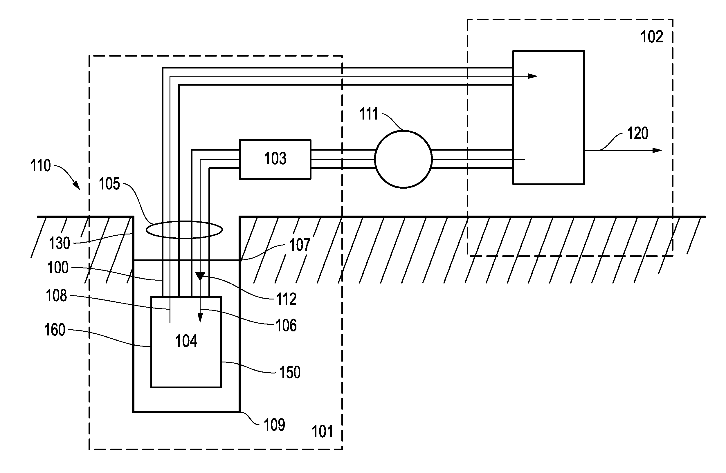
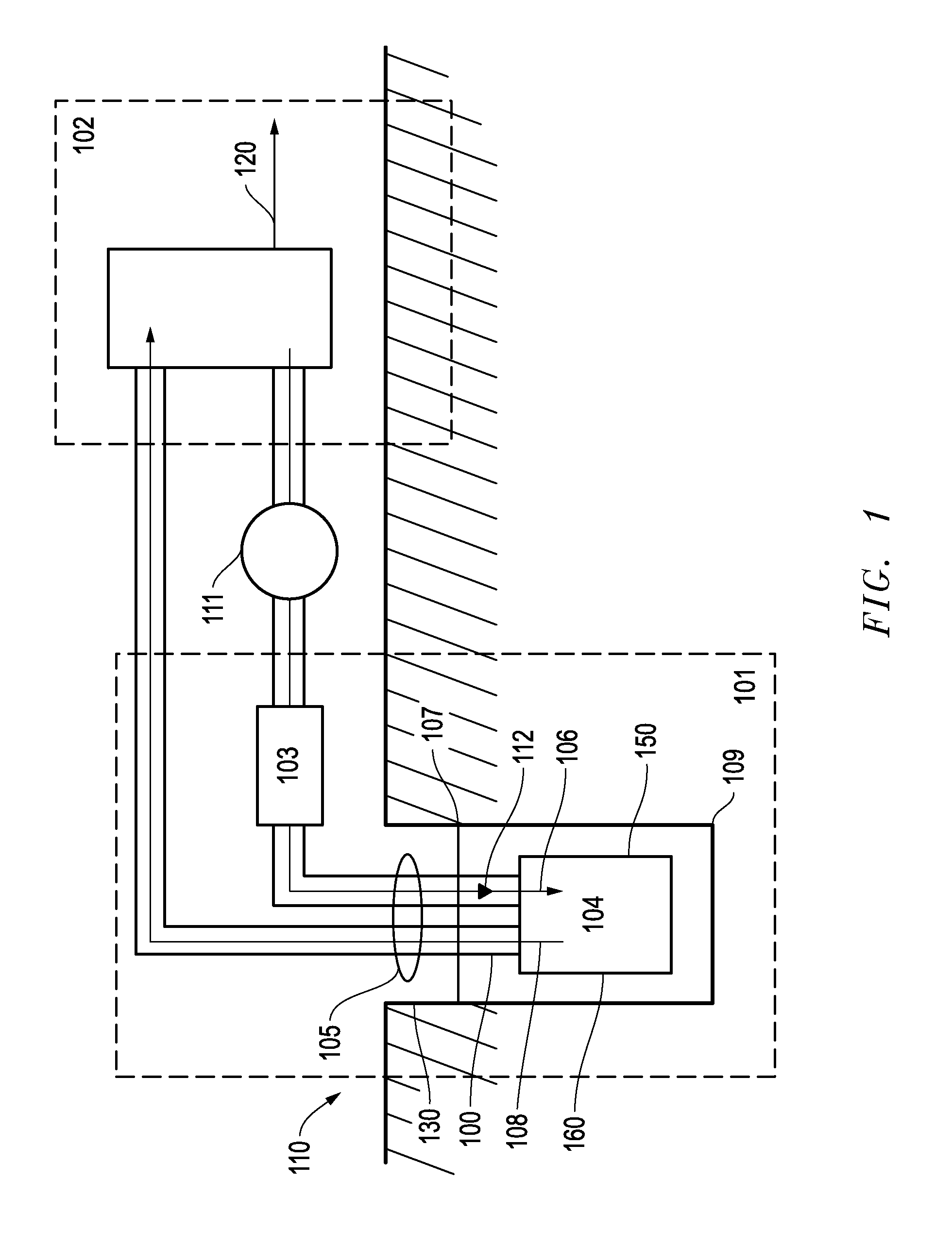
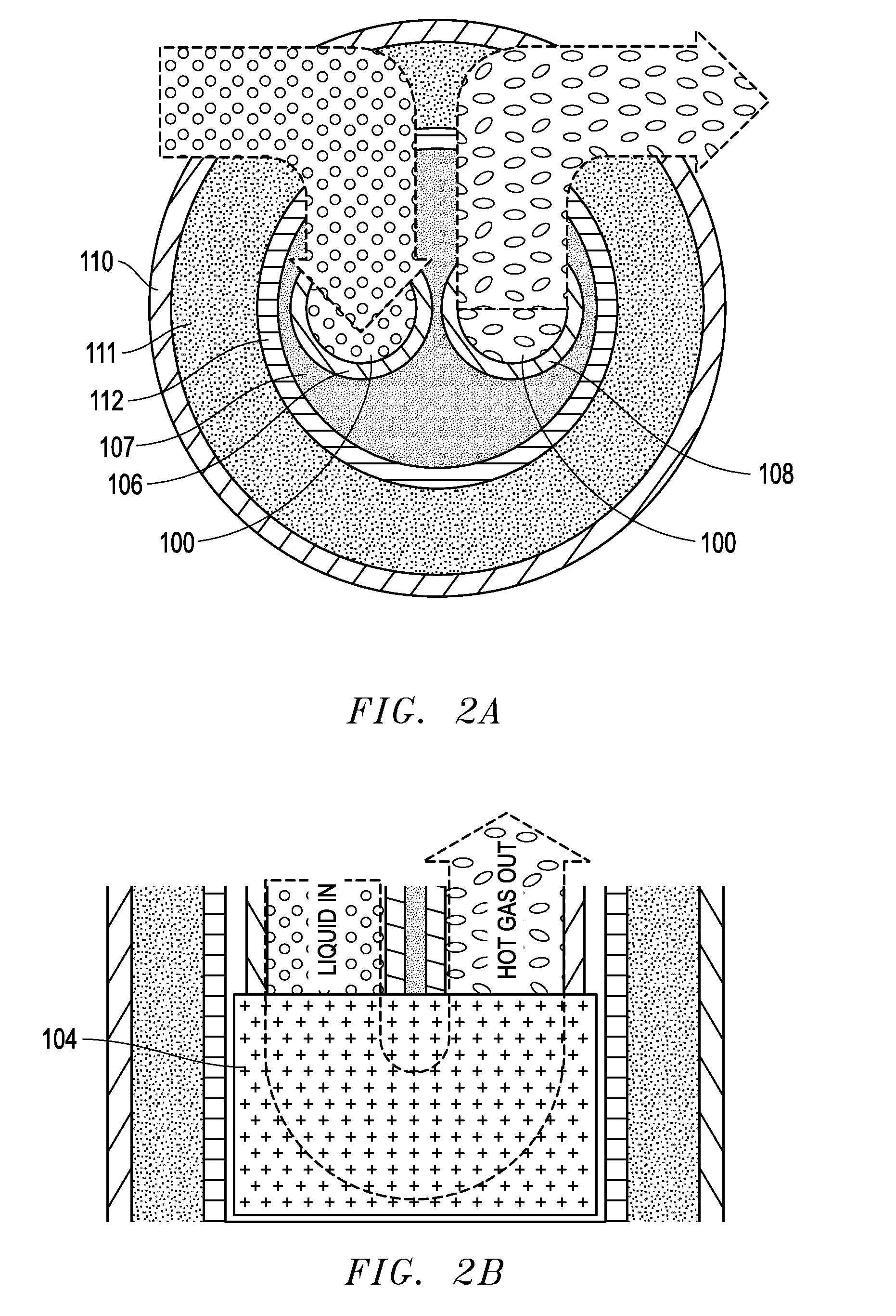
A method and system for extracting geothermal heat from a well is provided, wherein the well casing has positioned therein an inner pipe nested within an outer pipe. The space between the well casing and the outer pipe may be filled with an insulating medium. A liquid heat conducting material flows into and down through the inner pipe. The inner pipe may be fitted with a one-way valve so that the liquid heat conducting material does not reverse direction and flow upwards towards the surface. As the liquid heat conducting material approaches the bottom of the inner pipe, it enters into a heat exchanger, absorbs heat and transforms to its gaseous state. The gas rises upward through the space between the outer pipe and the inner pipe and into the electricity generating component.

Description

CROSS-REFERENCE TO RELATED APPLICATIONS[0001]This application claims priority based upon prior U.S. Provisional Patent Application Ser. No. 61 / 994,186 filed May 16, 2014 in the name of Richard L. Wynn, Jr., entitled “SYSTEM AND METHOD FOR UTILIZING OIL AND GAS WELLS FOR GEOTHERMAL POWER GENERATION,” the disclosure of which is incorporated herein by reference.BACKGROUND OF THE INVENTION[0002]The present invention relates generally to the field of converting geothermal energy into electricity or other forms of work. More specifically, the present invention relates to capturing geothermal heat from deep within a drilled well and bringing this geothermal heat to the earth's surface to generate work, for example in the form of electricity, in an environmentally friendly process.[0003]Wells that have been drilled for oil and gas exploration that are either depleted, or have never produced oil or gas, usually remain abandoned and / or unused and may eventually be filled. Such wells were crea...

Claims


Application Information

Patent Timeline
IPC IPC(8): F24J3/08
CPCF24J3/08F25B30/06F24T10/17Y02E10/10F24T10/00
Inventor WYNN, JR., RICHARD L.
Owner WYNN JR RICHARD L
Learn More