
Method for manufacturing a roller, adapted to equip a mechanical system forming a cam follower or a rocker arm

a manufacturing method and roller technology, applied in the direction of mechanical control devices, instruments, gearing, etc., can solve the problems of difficult oil leakage, achieve the effects of reducing friction, reducing oil leakage by centrifugal effect, and improving mechanical system functioning and li

Active Publication Date: 2015-11-19
AB SKF
View PDF10 Cites 4 Cited by
  • Summary
  • Abstract
  • Description
  • Claims
  • Application Information

AI Technical Summary

Benefits of technology

The invention reduces oil leakage in a mechanical system equipped with a roller by creating concentric tracks on the roller's surfaces. This improves lubrication and reduces friction, resulting in better functioning and longer lifespan of the mechanical system.

Problems solved by technology

Whereas random traces are likely to facilitate oil leakage along the lateral faces, concentric traces make oil leakage more difficult, thus improving lubrication.

Method used


Image

  • Method for manufacturing a roller, adapted to equip a mechanical system forming a cam follower or a rocker arm
  • Method for manufacturing a roller, adapted to equip a mechanical system forming a cam follower or a rocker arm
  • Method for manufacturing a roller, adapted to equip a mechanical system forming a cam follower or a rocker arm

Examples


Embodiment Construction

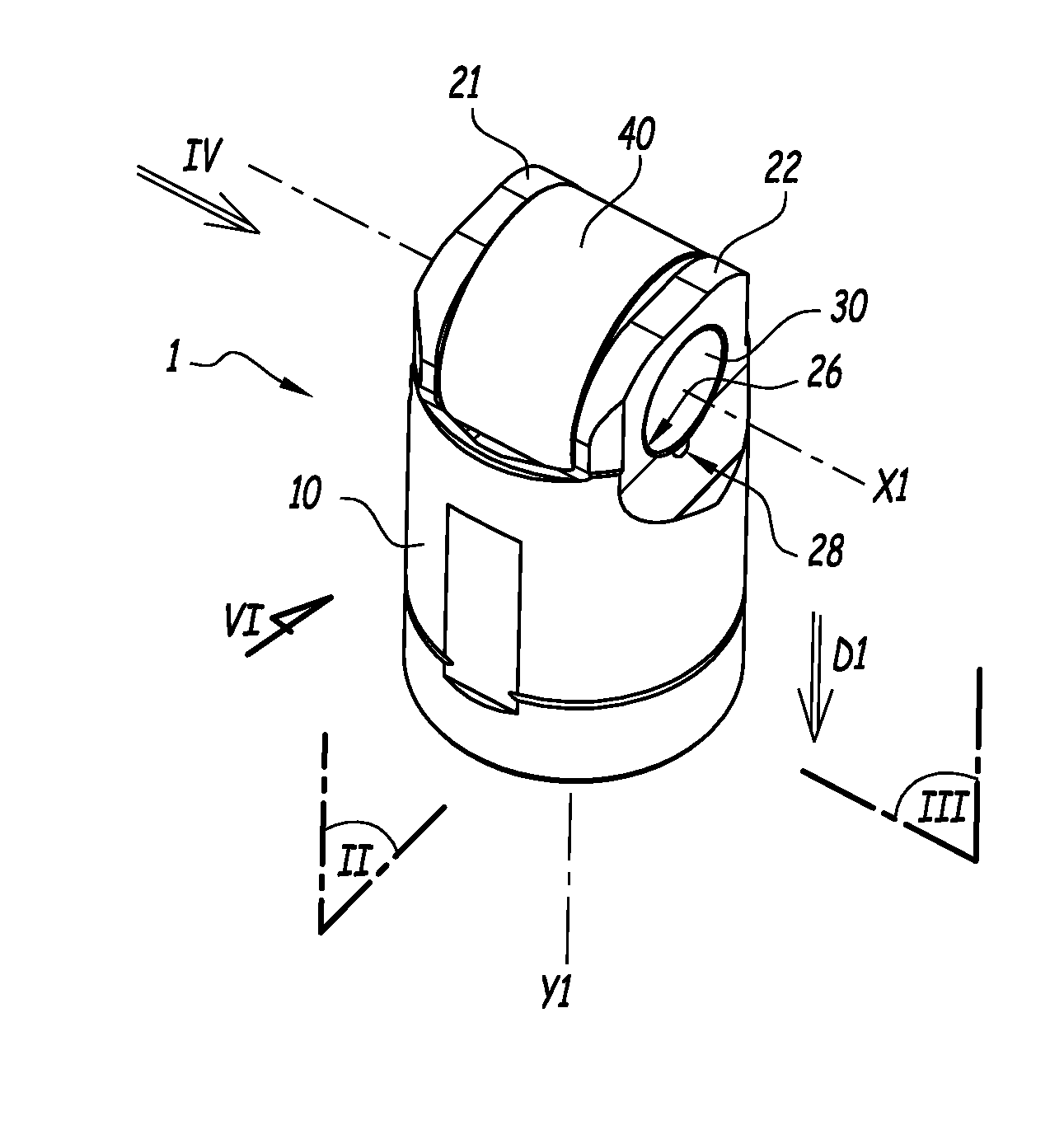
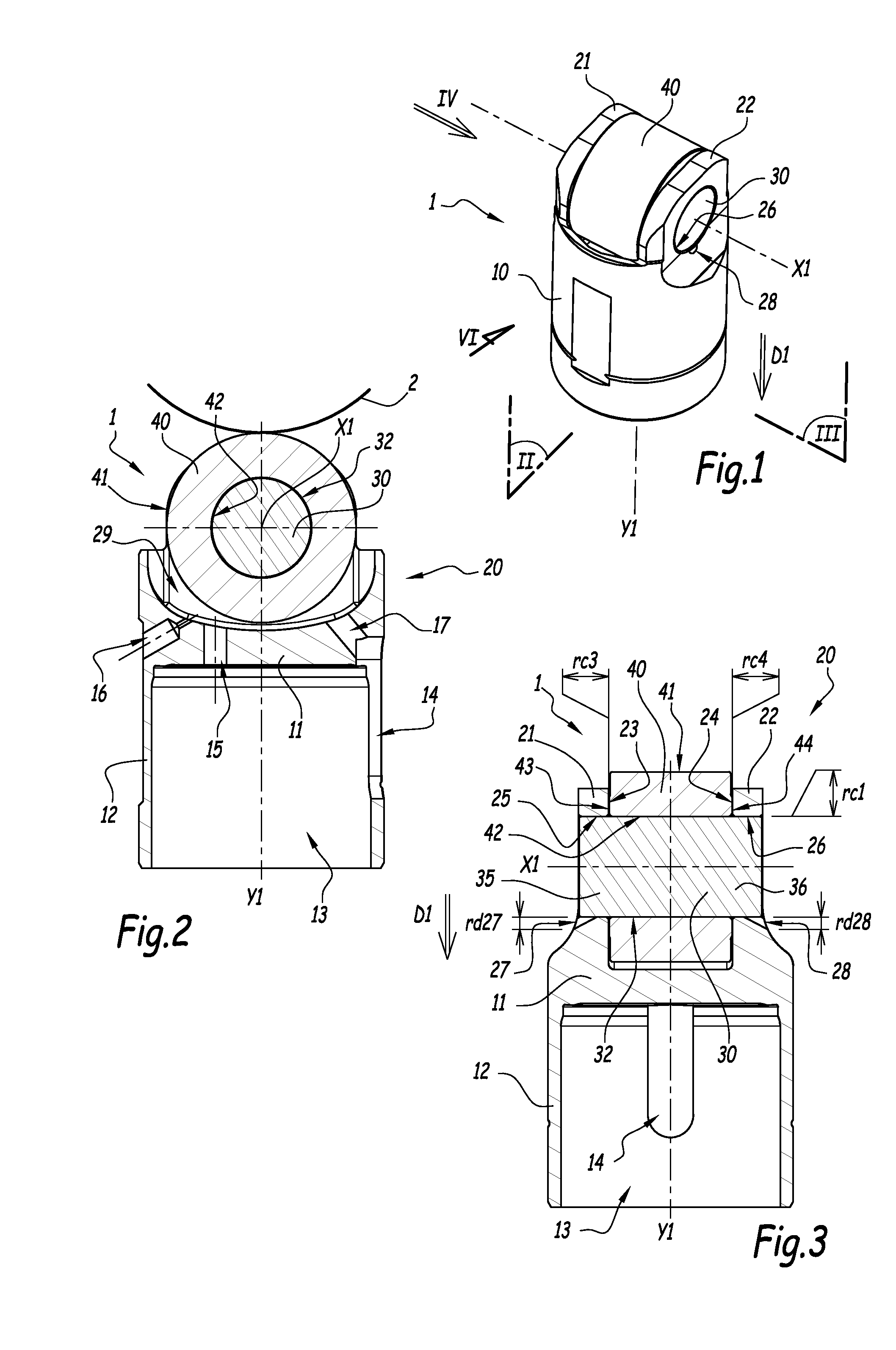
[0039]The mechanical system 1 represented on FIGS. 1 to 3 is of the cam follower type, adapted to equip an injection pump for a motor vehicle, preferably for a diesel truck engine, not shown.

[0040]System 1 comprises a tappet 10, a pin 30 and a roller 40, together forming a plain bearing. In heavy duty applications such as in diesel truck engines, there is a lack of space for the implementation of a rolling bearing, thus justifying the use of a plain bearing. Pin 30 and roller 40 are centered on a transverse axis X1, while tappet 10 is centered on a longitudinal axis Y1. Axis X1 and Y1 are perpendicular. The roller 40 is adapted to roll on a cam 2, shown on FIG. 2.

[0041]Tappet 10 comprises a central portion 11 interposed between a cylindrical portion 12 and a bearing portion 20. Portion 12 is centered on axis Y1 and delimits a cavity 13 inside tappet 10. This cavity 13 is adapted to receive a shaft, not shown, for moving tappet 10 along axis Y1. Tappet 10 forms a support element for ...


PUM

PropertyMeasurementUnit
mechanicalaaaaaaaaaa
widthaaaaaaaaaa
roughnessaaaaaaaaaa

Abstract

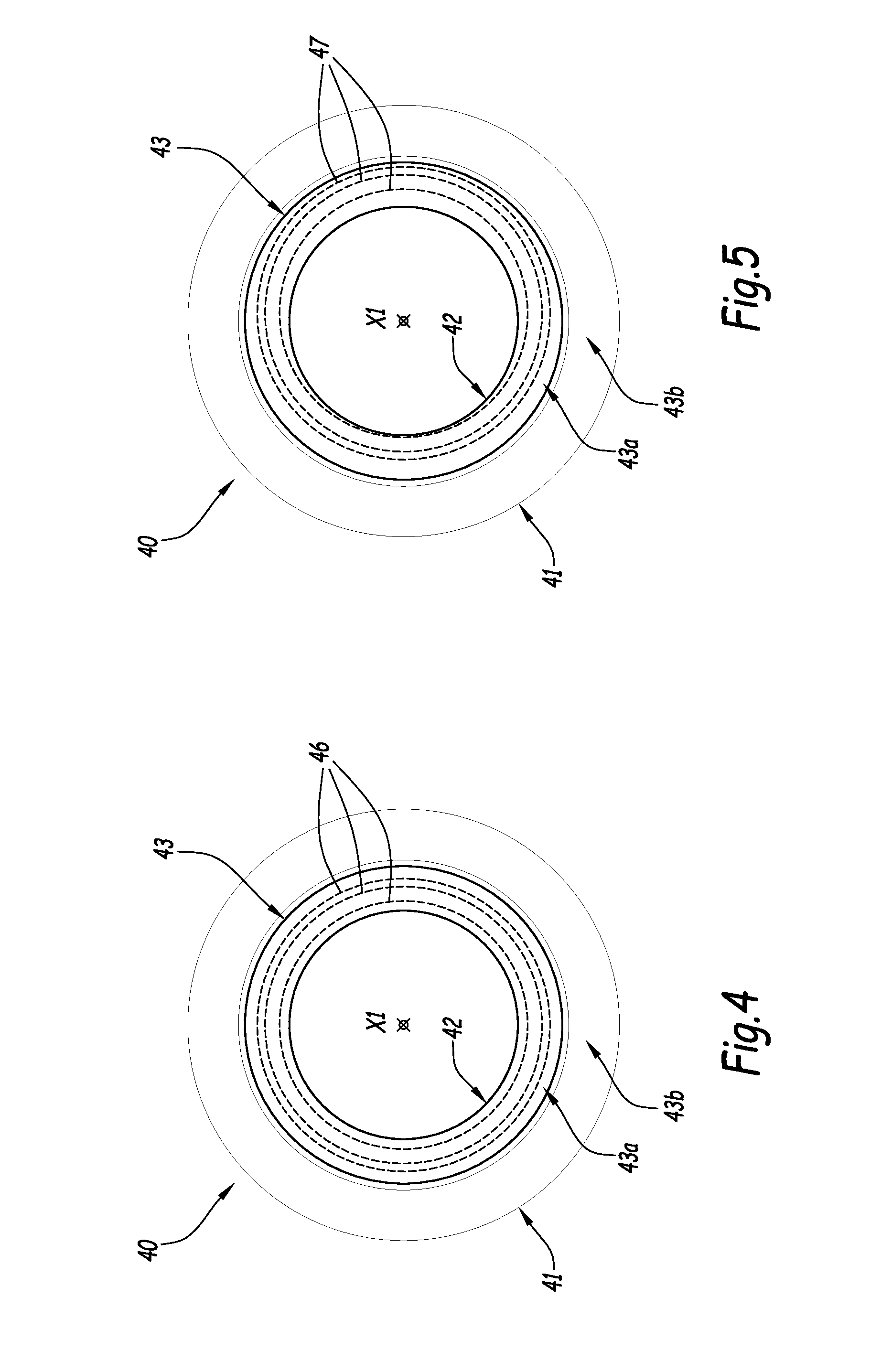
A method for manufacturing a roller, adapted to equip a mechanical system forming a cam follower or a rocker arm. The roller is centered on a central axis and comprising: an outer cylindrical surface adapted to roll on a cam, an inner cylindrical bore adapted to receive a pin belonging to the mechanical system, and two lateral faces extending radially to the central axis. The method includes a machining step forming circular grooves that are concentric with each other on at least one of the lateral faces of the roller. The roller can be installed within a mechanical system.

Description

CROSS REFERENCE TO RELATED APPLICATIONS[0001]This is a Non-Provisional Patent Application, filed under the Paris Convention, claims the benefit of European Patent (EP) Application Number 14305697.6 filed on 13 May 2014 (13.05.2014), which is incorporated herein by reference in its entirety.TECHNICAL FIELD OF THE INVENTION[0002]The invention concerns a method for manufacturing a roller, adapted to equip a mechanical system forming a cam follower or a rocker arm. The invention also concerns a mechanical system comprising such a roller. The invention also concerns an injection pump or a valve actuator, comprising such a mechanical system.BACKGROUND OF THE INVENTION[0003]EP-A-2 607 636 describes an example of a cam follower for an injection pump.[0004]Classically, a cam follower comprises at least a tappet, a pin and a roller. The pin and the roller are centered on a transverse axis, while the tappet extends along a longitudinal axis. The tappet is formed with two lateral flanges, delim...

Claims


Application Information

Patent Timeline
Patent Type & Authority Applications(United States)
IPC IPC(8): F01L1/14B23D79/00B24B7/17F01L1/18F02M59/10
CPCF01L1/14F01L1/18F02M59/102B24B7/17Y10T408/03Y10T74/20582Y10T74/2107Y10T29/49567B23D79/00F01L1/143F01L1/181F01L1/185F02M59/44F02M59/48F16H25/125B24B19/028F16H53/06Y10T29/49544F01L2305/02F01L2307/00F01L2303/00F01L2305/00
Inventor HAUVESPRE, BENO TMAFFUCCI, JULIEN
Owner AB SKF
Learn More