Energy chassis and energy exchange device

a technology of energy chassis and energy exchange device, which is applied in the direction of heat storage plants, ac network voltage adjustment, domestic heating details, etc., to achieve the effect of simplifying the design and construction of the building energy system, efficient meeting building energy requirements, and increasing the efficiency of building heating and cooling systems

Active Publication Date: 2015-11-05
GREENSLEEVES TECH CORP
View PDF4 Cites 5 Cited by
  • Summary
  • Abstract
  • Description
  • Claims
  • Application Information

AI Technical Summary

Benefits of technology

The present invention provides a simple to implement, multifunctional, factory produced, self-contained heating and cooling system for buildings that is designed to meet energy requirements more efficiently. The system incorporates methods and devices for automated energy management, including real-time and future energy requirement projections, energy sensing, load forecasting, and storage and management of energy. The system is also designed to be easily customized to the implementation. Additionally, the invention provides a next generation geothermal heat exchanger that can be used in a standalone configuration or in combination with other thermal energy storage systems to increase the performance of the geothermal system while reducing installation costs. The invention also allows for the integration of multiple sources of energy, such as solar, geothermal, and fuel cells, to reduce the amount of capital required to build the entire system and make each source available in a reservoir, so that it may be reliably used according to projected system needs and optimization calculations.

Problems solved by technology

Energy consumption in commercial buildings is a very expensive component of the cost for operating and maintaining a building.
For example, commercial buildings have expensive air conditioning and heating needs which over the lifetime of the building often add up to more than double the first cost for construction.
Attempts over the years to reduce energy consumption have resulted in adding substantial increases in construction costs which are not recouped over the short term.
The typical commercial building heating and cooling system used in the U.S. today is a Variable Air Volume (VAV) system, typically configured this system cannot utilize sustainable energy sources.
Buildings represent 40% of the energy used in the U.S. and are fueled almost entirely with fossil fuels that are expensive and damaging to the environment.
There are a number of problems that make these HVAC systems energy inefficient, unhealthy, uncomfortable, and that create barriers to adopting new technologies.
These problems include:Pressure on construction costs encourages owners to keep up front costs low by purchasing inexpensive, wasteful HVAC systemsWasting excess energy rejected through chillers, etc. rather than moving it to where it is needed or storing it for later useHigh energy movement through walls because of inadequate insulation—in conventional systems the shell is not part of the solution, but in the invention it can be made to be an energy storage deviceConstantly reheating and re-cooling the building mass rather than holding it at temperatureOverbuilt, inefficient systems that could be made much smallerThe inability to use local energy (e.g. solar, body heat, etc.)Heating the building when the heating system is least efficient and likewise cooling the building when the cooling system is least efficient—with energy storage, this can be reversed to increase efficiencyGeothermal systems are typically more costly to build and their function is not designed to maximize efficiency which in turn reduces the use of these systems
The rapidly changing alternative energy technologies that are being developed are created in silos to perform the functions of that technology and do not work together without custom integration.
These often prove to be unreliable or fail.
Few engineering firms have the resources to research and integrate innovative solutions and as a result do not commonly design them into client buildings.
The custom-build process is very expensive and limits market use while the standardized product brings down costs and expands the market.
While we are aware that there is a great deal of energy available locally (e.g. body heat, lighting heat, computer heat, solar thermal, solar photovoltaic, geothermal, etc.) the U.S. has failed to adopt a significant use of local energy harvesting (i.e. alternative or renewable energy).
Current geothermal heat exchanger design is not optimized to provide cooler water to support sensible cooling devices such as radiant cooling panels and chilled beams.
Instead, they mix higher and lower temperature water together which reduces the ability to provide sensible cooling with these devices.
Additionally, current geothermal heat exchanger design is not configured to maximize the ability to store energy for later use by mixing / combining various heat exchanger configurations.
This method does not allow for loops to be separated for different uses; it combines all inputs and all outputs into a two pipe (one in, one out) system.
As it does not combine these inputs, it cannot reach the most efficient energy use solution.

Method used


Image

  • Energy chassis and energy exchange device
  • Energy chassis and energy exchange device
  • Energy chassis and energy exchange device

Examples


Embodiment Construction

[0060]Before explaining the disclosed embodiments of the present invention in detail it is to be understood that the invention is not limited in its application to the details of the particular arrangements shown since the invention is capable of other embodiments. Also, the terminology used herein is for the purpose of description and not of limitation.

[0061]The following is a list of reference numerals used in the description and the drawings to identify components:

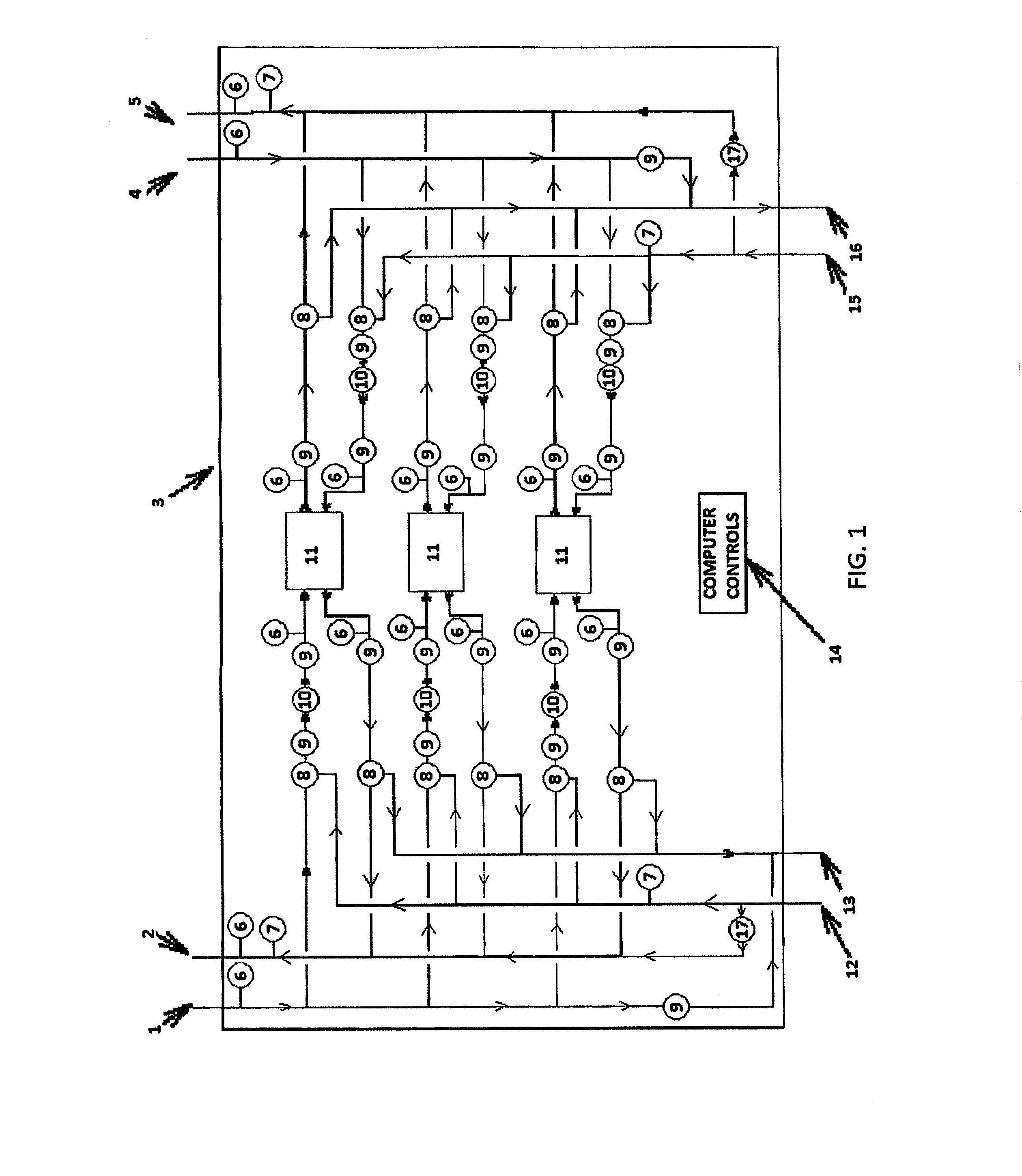
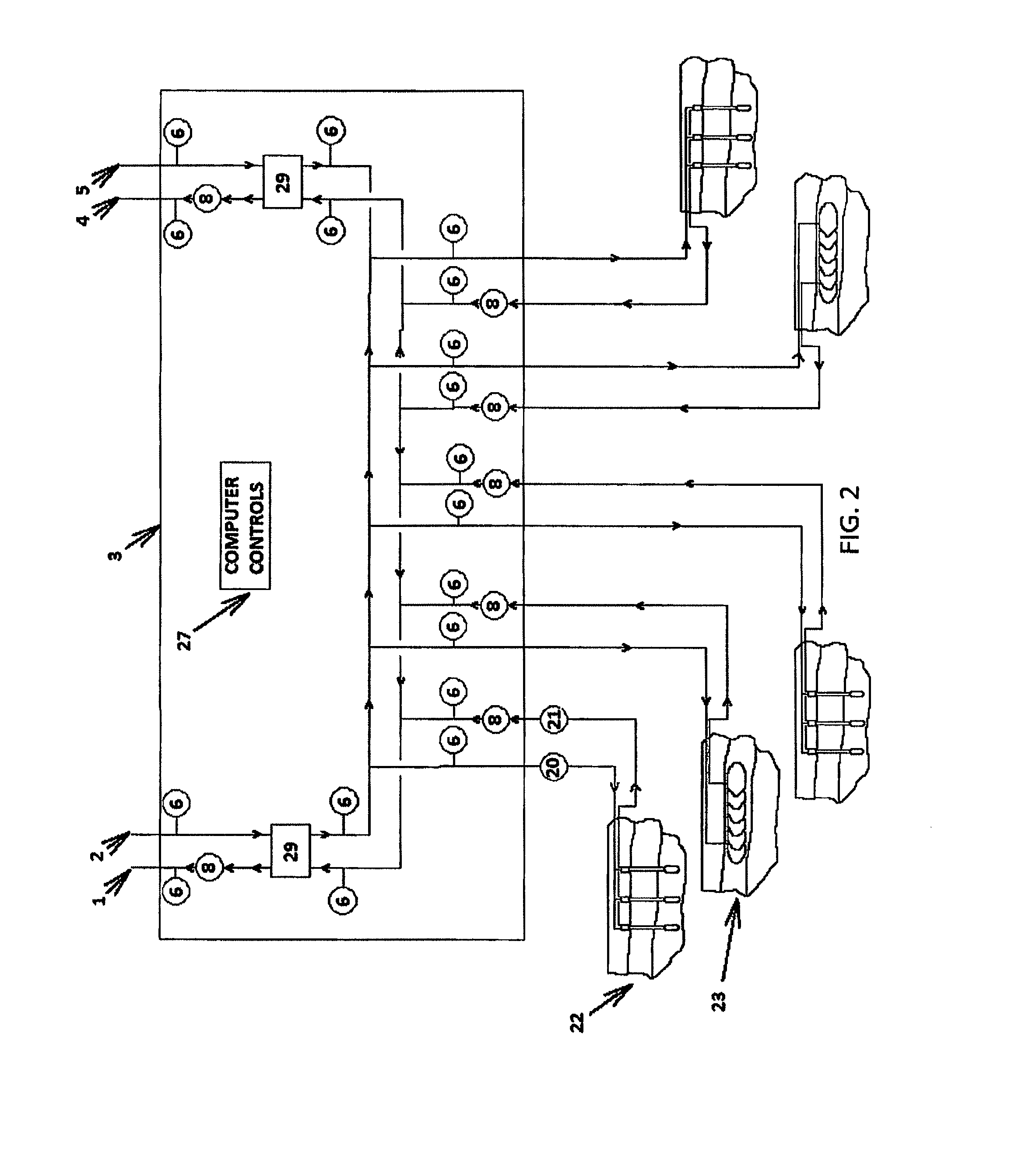
1hot fluid return2hot fluid source3energy chassis4cold fluid return5cold fluid source6temp. indicator and sensor7flow meter8three-way control valve9isolation valve10variable volume circulation pump11fluid-to-fluid refrigeration-based heat pump12supply from “warm” side of energy exchange device13return connection to “warm” side of energy exchange device14computer-based control system15supply connection from “cool” side of energy exchange device16return connection to “cool” side of energy exchange device17variable volume ...


PUM


Abstract

Systems, methods and devices for utilizing an energy chassis device designed to sense, collect, store and distribute energy from where it is available using devices that harvest or convert energy to locations requiring energy such as but not limited to HVAC (heating, ventilation and cooling) systems. The systems, methods and devices can also be used with a next generation geothermal heat exchanger that achieves higher energy harvesting efficiency and provides greater functionality than current geothermal exchangers.

Description

CROSS REFERENCE TO RELATED APPLICATIONS[0001]This application is a continuation of U.S. patent application Ser. No. 13 / 101,771, filed May 5, 2011, titled “ENERGY CHASSIS AND ENERGY EXCHANGE DEVICE,” now U.S. Pat. No. 9,080,789, which is herein incorporated by reference in its entirety.[0002]U.S. patent application Ser. No. 13 / 101,771 claims the benefit of U.S. Provisional Patent Application No. 61 / 331,525, filed May 5, 2010 and titled “ENERGY CHASSIS AND ENERGY EXCHANGE DEVICE.”FIELD[0003]This invention relates to building, heating and cooling systems (HVAC) systems and electrical systems, in particular to systems, methods, and devices used to sense and collect local sources of naturally renewable energy, to store energy and to redistribute energy to efficiently meet building needs by using a fully integrated, factory assembled device.BACKGROUNDEnergy Consumption Costs and Problems[0004]Energy consumption in commercial buildings is a very expensive component of the cost for operatin...

Claims


Application Information

Patent Timeline
Patent Type & Authority Applications(United States)
IPC IPC(8): F24J3/08
CPCF24J2003/089F24J3/08F24D12/02F24D2200/11F24D2200/12F24D2200/22F24F2005/0057F28D20/00F28F2200/00Y02E70/30G06Q10/04G06Q50/06Y02B70/3225Y02B10/70Y04S20/222Y04S20/244Y02B30/52F24F11/46F24T10/10F24T2010/56F24T2201/00H02J2310/12H02J2310/14H02J3/14F24T10/00Y02B30/00Y02B30/70Y02B70/30Y02E10/10Y04S20/242Y02B10/40Y02E60/14
Inventor HAMSTRA, STEPHEN A.LINN, W. MICHAEL
Owner GREENSLEEVES TECH CORP
Why Eureka
Try Eureka