Powerful toy blower

a blower and toy technology, applied in the field of air blowers, can solve the problems of weak fan capacity, unstable operation, unneeded vibration, etc., and achieve the effects of facilitating heat dissipation and air flow, enhancing the volume of air flow and fan capacity, and stable operation

Inactive Publication Date: 2015-10-29
SHIN DORN
View PDF4 Cites 0 Cited by
  • Summary
  • Abstract
  • Description
  • Claims
  • Application Information

AI Technical Summary

Benefits of technology

The patent is for a powerful toy blower that has a big fan, a generous air volume, and is designed to dissipate heat effectively. The goal is to create a long-lasting toy that can be used for many years.

Problems solved by technology

As this kind of design is not of eccentric structure, the volume of air flow is small and the fan capacity is weak.
In some cases, the motor is not disposed properly near the center of the housing, resulting in unstable operation and unnecessary vibration.
Also, there is not yet a mounting socket inside the housing for the motor, which is used to be disposed outside the housing, resulting in larger size of the entire blower.
In other cases, the air inlets for the motor fixing socket are too small for air flow; they cannot properly exhaust waste heat as well as provide air needed for the fan, which will in turn shorten the service life of motor.
Further, there has not yet been a design of toy blower that the fan blades are tangent to the annular hub and that the edges of fan blades are vertical to the periphery of the rotating plate.
This will cause problems of more resistance to fan blades, smaller air volume, backflow of air and lower fan capacity.
There has still not yet been a design that places the motor in conjunction with the fan blades.
A separate motor chamber will have to settle for bulkier size of blower and higher cost of production.
This specific design will save space, reducing the overall size of the blower and the cost of production.

Method used


Image

  • Powerful toy blower
  • Powerful toy blower
  • Powerful toy blower

Examples


Embodiment Construction

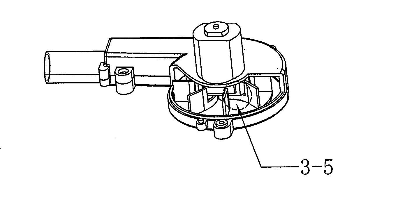
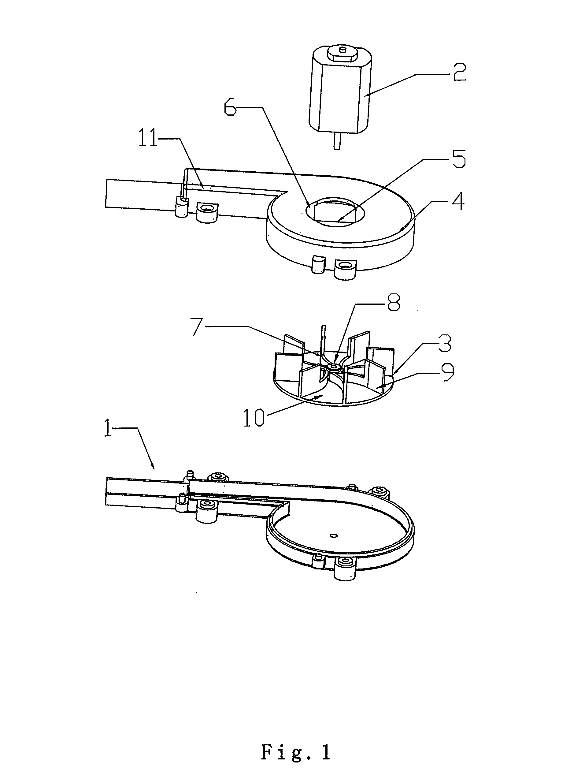
[0019]The embodiment of the utility model, a powerful toy blower as shown on FIG. 1, comprises three basic parts, including a housing 1 that has an air outlet, a motor 2 and a fan 3 that is disposed in the housing. The housing 1 is composed of an upper and a lower half shells. Inside the housing 1 are a fan chamber and an air flow channel 11. The fan 3 is disposed in the said fan chamber with a centrifugal design that the center of the annular hub of the fan 3 is away from the center of the fan chamber in the housing 1.

[0020]On the upper shell 4 is there a motor fixing socket 5, with two air inlets 6 located at opposite sides of the said motor fixing socket 5. A motor mounting socket 7 is disposed within the center top of the fan 3. The motor 2 is to be installed in the motor mounting socket 7 through the motor fixing socket 5. As all the parts put together and the power turned on, the motor 2 drives the fan 3 to rotate at high speeds, producing strong air flow.

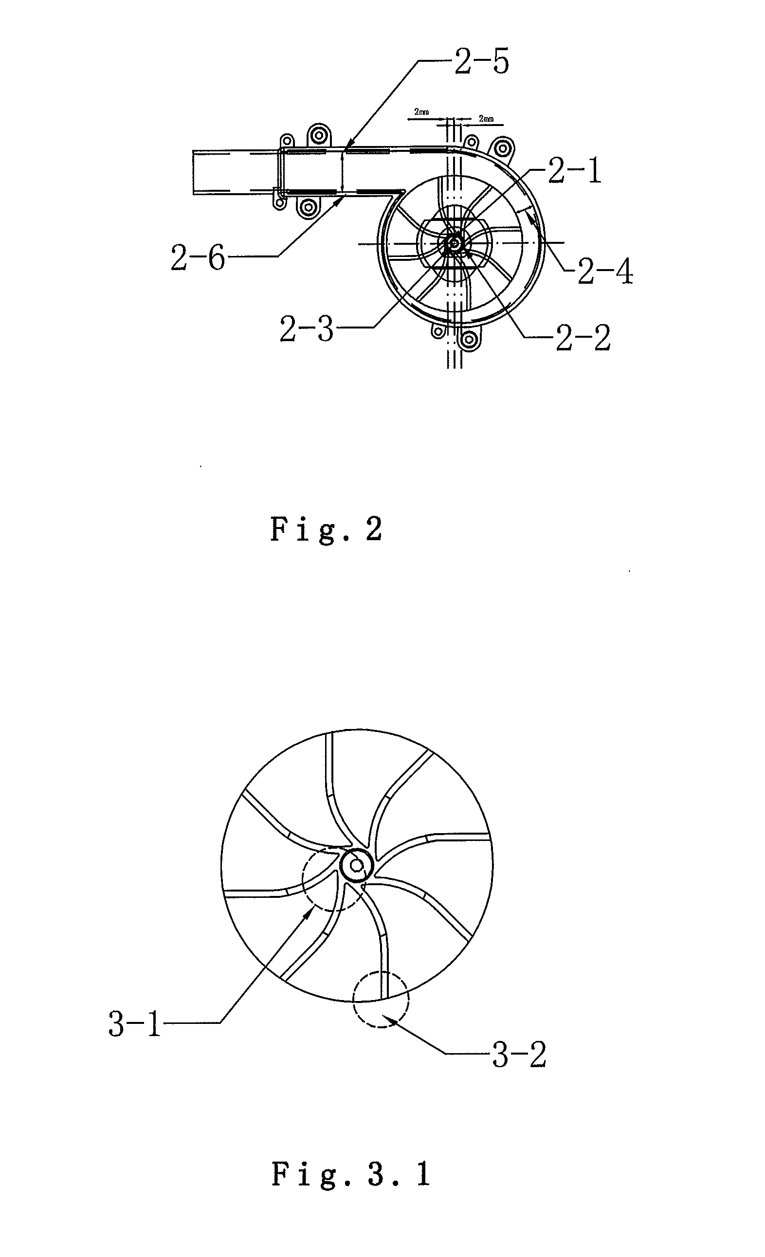
[0021]Referring to FI...


PUM


Abstract

The embodiment of the utility model discloses a powerful toy blower, comprising a housing, a fan and a motor. Application of Bernoulli's Principle enhances the efficiency of air flow. The housing adopts centrifugal design, with which the fan shall easily rotate at high speeds and air resistance to the fan will be much lower, leading to higher fan capacity. On the housing shell near a motor fixing socket, two air inlets are disposed for efficient heat dissipation and sufficient air flow so that the service life of the blower can be extended. The fan is shaped based on geometric modeling. The fan blades are tangent to the annular hub and perpendicular to the periphery of the rotating plate. Also, the edge of each blade at the periphery is vertical to the rotating plate, so as to reduce air leakage and avoid air backflow. A motor mounting socket is disposed within the center top of the rotating plate, which not only enhances operation stability and avoid unnecessary vibration but also reduces the size of the housing and the cost of production.

Description

TECHNICAL FIELD OF THE INVENTION[0001]The utility model relates to the field of air blower, in particular to a powerful toy blower.BACKGROUND OF THE INVENTION[0002]In the current market, the design of toy blower is without the application of centrifugal design and has only a circular fan chamber for the fan, with the center of the annular hub in line with the center of the fan chamber. As this kind of design is not of eccentric structure, the volume of air flow is small and the fan capacity is weak.[0003]In some cases, the motor is not disposed properly near the center of the housing, resulting in unstable operation and unnecessary vibration. Also, there is not yet a mounting socket inside the housing for the motor, which is used to be disposed outside the housing, resulting in larger size of the entire blower. In other cases, the air inlets for the motor fixing socket are too small for air flow; they cannot properly exhaust waste heat as well as provide air needed for the fan, whic...

Claims


Application Information

Patent Timeline
Patent Type & Authority Applications(United States)
IPC IPC(8): F04D25/08F04D29/42F04D25/06
CPCF04D25/082F04D29/4226F04D25/0606F04D25/084F04D29/5806
Inventor LI, JIAHONG
Owner SHIN DORN
Why Eureka
Try Eureka