Prefiltering in MIMO Receiver

a technology of mimo receiver and prefiltering, which is applied in diversity/multi-antenna system, amplitude demodulation, and baseband system details, etc., can solve the problems of bit and block errors on information transmitted, and achieve low computational complexity, efficient isi processing, and reduced computational complexity of demodulator of receiver.

Active Publication Date: 2015-10-22
TELEFON AB LM ERICSSON (PUBL)
View PDF19 Cites 1 Cited by
  • Summary
  • Abstract
  • Description
  • Claims
  • Application Information

AI Technical Summary

Benefits of technology

[0029]In other words, is a MIMO pre-filter in a receiver is provided which results in a channel matrix which is upper triangular and with minimum phase filters on its main diagonal. A minimum phase polynomial has the following energy compaction property: for any the sum of the energy contained in the first k taps is larger than the energy contained in the first k taps of any other polynomial having the same spectrum. The polynomial coefficients correspond to channel tap values in the equalizer of a receiver in which the method is realized. Therefore, the MIMO pre-filter of the present disclosure reduces the channel to a triangular form while at the same time reshapes the diagonal entries by compacting the channel energy. Both triangularization and energy compaction are very useful properties in order to reduce the computational complexity of the demodulator of a receiver in which the method is realized.
[0030]Such a MIMO pre-filter is an essential com

Problems solved by technology

This communication channel is often referred to as an air interf

Method used


Image

  • Prefiltering in MIMO Receiver
  • Prefiltering in MIMO Receiver
  • Prefiltering in MIMO Receiver

Examples


Embodiment Construction

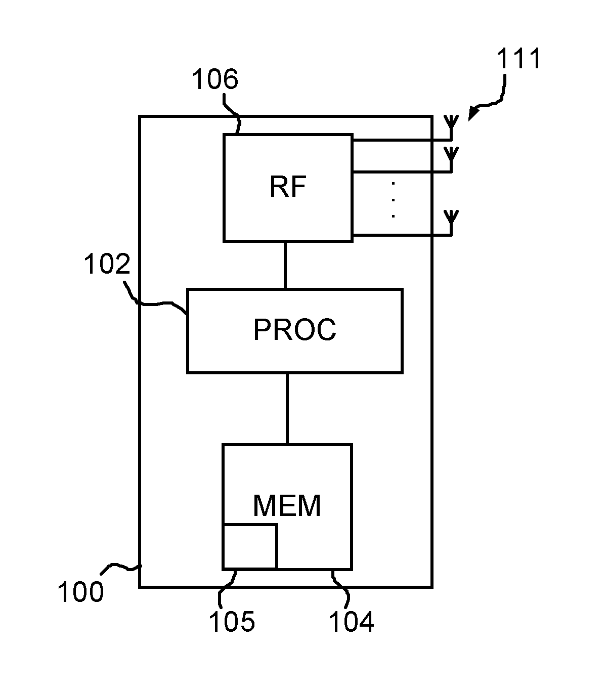
[0041]FIG. 1 illustrates schematically a MIMO enabled mobile communication terminal 100 comprising a processor 102, a memory 104, radio frequency, RF, receiving and transmitting circuitry 106 and a plurality of antenna elements 111. Radio communication via the antennas 111 is realized by the RF circuitry 106 controlled by the processor 102, as the skilled person will understand. The processor 102 makes use of software instructions 105 stored in the memory 104 in order to control all functions of the terminal 100, including the functions of receiver circuitry in the RF circuitry 106 to be described in detail below with regard to demodulation. In other words, at least the RF circuitry 106, the processor 102 and the memory 104 form parts of control and communication circuitry that is configured to control demodulation as summarized above and described in detail below. Further details regarding how these units operate in order to perform normal functions within a mobile radio communicat...


PUM


Abstract

Data signals transmitted by a plurality of transmitting antennas over a radio channel are demodulated. The method comprises receiving (202) on a plurality of receiving antennas, a data signal and a reference signal, the contents of the reference signal being known a priori to the receiver. The contents of the reference signal are used for calculating (204) an estimated polynomial channel matrix. A polynomial pre-filter matrix is calculated (206, 208) by a decomposition of the estimated polynomial channel matrix into a product of a paraunitary polynomial matrix and an upper triangular polynomial matrix with minimum phase filters on its main diagonal, where the polynomial pre-filter matrix is obtained by calculating the paraconjugate of the paraunitary polynomial matrix. The received data signal is demodulated (212) where the received data signal is multiplied with the calculated polynomial pre-filter matrix.

Description

TECHNICAL FIELD[0001]The field of the present disclosure is that of controlling a multiple input multiple output, MIMO, receiver. Specifically, calculations associated with determining the characteristics of the radio channel between a transmitter and the MIMO receiver in order to improve performance when demodulating received signals.BACKGROUND[0002]In mobile radio communication systems that use Multi-User MIMO, MU-MIMO, several users are scheduled to transmit simultaneously during the same time and frequency interval. These users can be distinguished by allocating different, and preferably orthogonal, reference signals to them such that all channels from all transmit antennas to all receive antennas can be estimated. The reference signals, or training sequence, are sequences known to the receiver and they are transmitted together with user signals such that the receiver can estimate distortions of the received signal after it is transmitted.[0003]MU-MIMO forms part of, e.g., the t...

Claims


Application Information

Patent Timeline
IPC IPC(8): H04B1/40H04B7/04H04L25/02H04L25/03
CPCH04B1/40H04L25/03H04L25/0246H04L25/0204H04L25/0228H04B7/0413H04B7/06H04B7/08H04L25/0242H04L25/03891H04L2025/03426
Inventor SAHLIN, HENRIKLOPEZ, MIGUEL
Owner TELEFON AB LM ERICSSON (PUBL)
Why Eureka
Try Eureka