
Implicit feed-forward compensated op-amp with split pairs

a compensation technique and op-amp technology, applied in differential amplifiers, amplifiers with semiconductor devices/discharge tubes, amplifier details, etc., can solve the problems of high degree of phase lag, conventional compensation techniques may not provide enough loop gain at low frequencies for some applications, etc., to achieve high gain and desired phase margin, small current, and high loop gain and stability performance

Inactive Publication Date: 2015-10-15
BOARD OF RGT THE UNIV OF TEXAS SYST
View PDF1 Cites 4 Cited by
  • Summary
  • Abstract
  • Description
  • Claims
  • Application Information

AI Technical Summary

Benefits of technology

The present invention provides a multi-stage feed-forward operational amplifier that is more efficient in size and power, and has high loop gain and stability performance. This is achieved by using an implicit feed-forward compensation technique for operational amplifiers with split pairs. The main FFC port is realized by the P-side of the CMOS input structure of the second and third stages of the op-amp, while the main signal path is through the N-side. The disclosed op-amp is unconditionally stable with adequate phase lead and can be used in highly linear applications operative at intermediate frequency, such as signal buffers for high-performance data converters or radio-frequency modulators and demodulators, continuous-time filters or sigma-delta data converters.

Problems solved by technology

Conventional compensation techniques may not provide enough loop gain at low frequencies for some applications, especially if implemented in reduced-scale semiconductor technologies, such as nanometer gate-length CMOS processes.
Moreover, extending such architecture to more than two stages, to increase the loop gain, typically results in a high degree of phase lag (e.g., 270° or more at the output), which presents stability concerns.

Method used


Image

  • Implicit feed-forward compensated op-amp with split pairs
  • Implicit feed-forward compensated op-amp with split pairs
  • Implicit feed-forward compensated op-amp with split pairs

Examples


Embodiment Construction

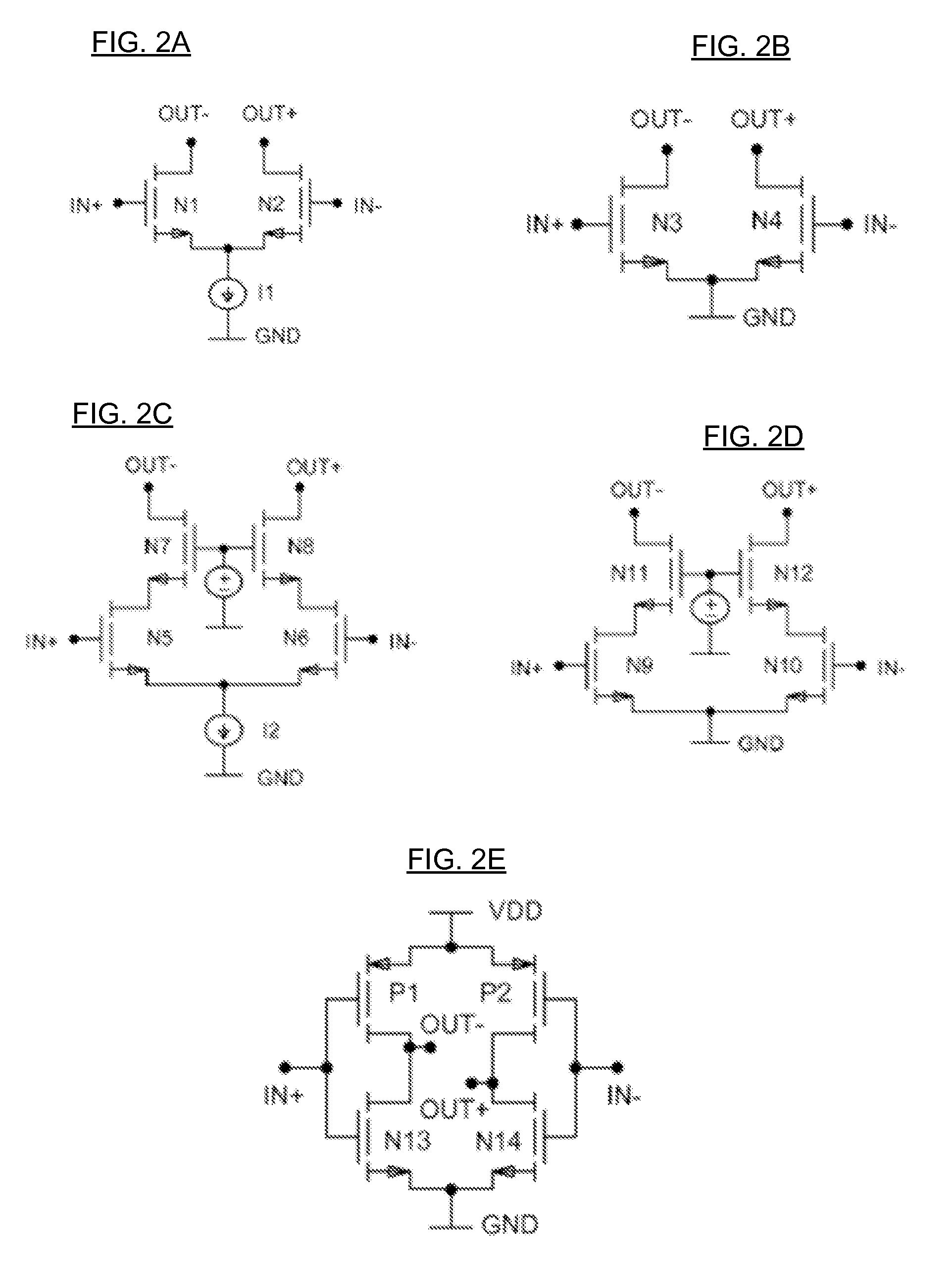
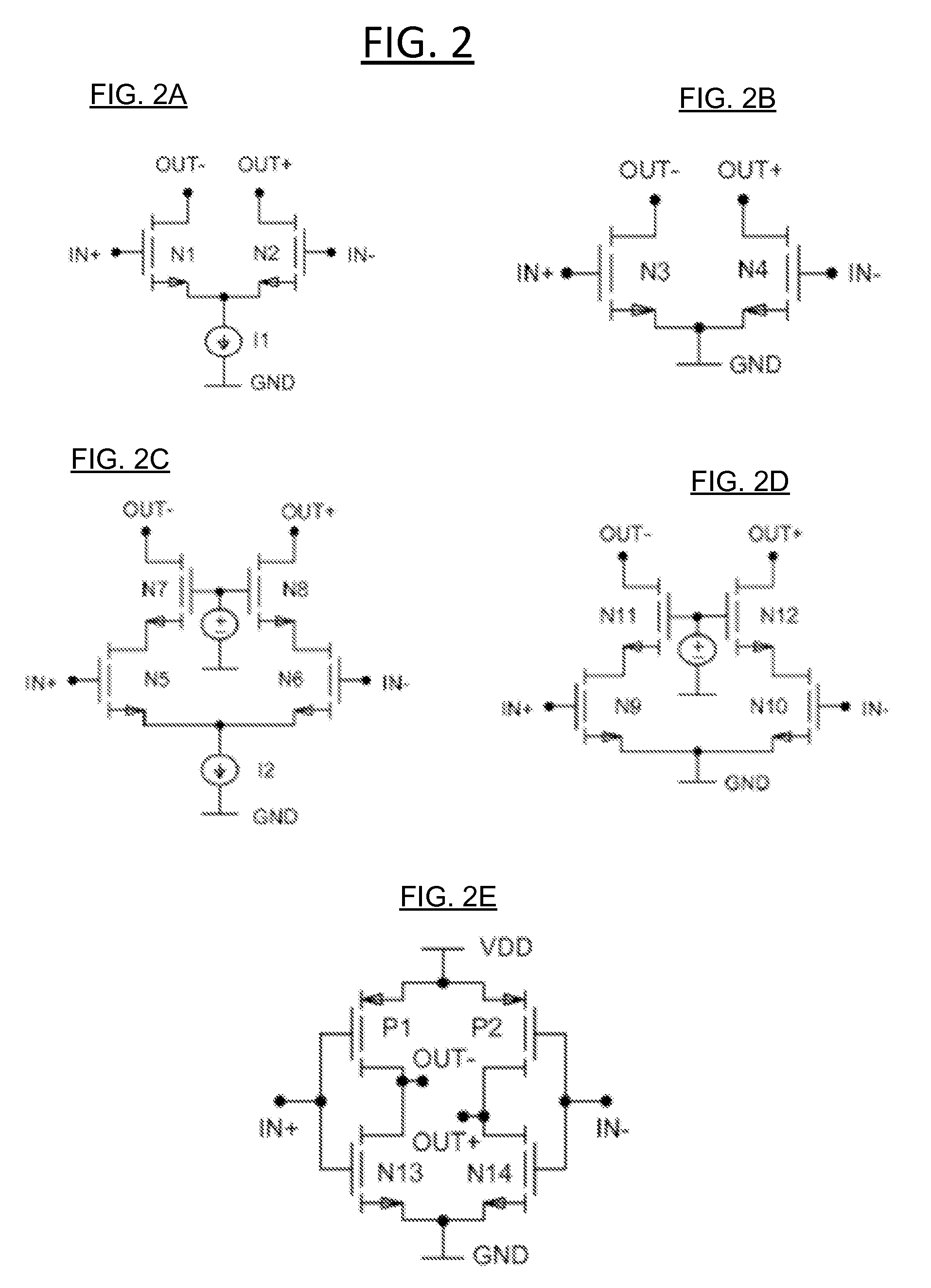
[0013]The present disclosure will now be described more fully hereinafter with reference to the accompanying drawings, which form a part hereof, and which show, by way of illustration, specific example embodiments. Subject matter may, however, be embodied in a variety of different forms and, therefore, covered or claimed subject matter is intended to be construed as not being limited to any example embodiments set forth herein; example embodiments are provided merely to be illustrative. Likewise, a reasonably broad scope for claimed or covered subject matter is intended. Among other things, for example, subject matter may be embodied as devices, components, methods or systems. The following detailed description is, therefore, not intended to be taken in a limiting sense.

[0014]Throughout the specification and claims, terms may have nuanced meanings suggested or implied in context beyond an explicitly stated meaning Likewise, the phrase “in one embodiment” as used herein does not nece...


PUM


Abstract

Disclosed are systems implementing an implicit Feed-Forward Compensated (FFC) op-amp, where the main FFC port is realized by the P-side of the CMOS input structure of the 2nd and 3rd stages of the op-amp, while the main signal path is through the N-side. According to some embodiments, to balance the relative strengths of the main path and feed-forward paths, the 2nd-stage NMOS input pair is split into two pairs, one is used to route the main path while the other is used for auxiliary FFC. The disclosed implicit FCC op-amp is unconditionally stable with adequate phase lead. According to some embodiments, the disclosed op-amp, which may be a wide-band op-amp, can be used in highly linear applications operative at intermediate frequency (IF), such as signal buffers for high-performance data converters or radio-frequency (RF) modulators and demodulators, continuous-time (CT) filters or sigma-delta data converters.

Description

[0001]This application includes material that is subject to copyright protection. The copyright owner has no objection to the facsimile reproduction by anyone of the patent disclosure, as it appears in the Patent and Trademark Office files or records, but otherwise reserves all copyright rights whatsoever.FIELD[0002]The present disclosure is generally related to multiple-stage operational amplifiers, and more particularly, for an implicit feed-forward compensation technique for operational amplifiers with split pairs to achieve high gain and desired phase margin simultaneously while drawing small current.RELATED ART[0003]Many different kinds of circuits utilize operational amplifiers to achieve desired functionality. For example, application circuits utilize operational amplifiers arranged in feedback configurations (e.g., negative or positive) to realize a predetermined gain or other mathematical functions over a selected frequency range. To prevent instability when used in such fe...

Claims


Application Information

Patent Timeline
Patent Type & Authority Applications(United States)
IPC IPC(8): H03F3/45
CPCH03F3/45179H03F2203/45222H03F2203/45116H03F2200/153H03F1/086H03F3/211H03F3/45183H03F3/45188H03F3/45237H03F3/4565H03F2200/408H03F2203/45236H03F2203/45418H03F2203/45481
Inventor CHIU, YUNWU, BO
Owner BOARD OF RGT THE UNIV OF TEXAS SYST
Learn More