
Methods and systems for providing battery feedback to patient

a battery feedback and patient technology, applied in the field of mechanically assisted circulation (mac) systems, can solve the problems of heart failure, inability to pump enough blood to your body, and inability to provide patient battery feedback, so as to avoid subjecting the patient to undue stress

Active Publication Date: 2015-10-15
TC1 LLC
View PDF4 Cites 10 Cited by
  • Summary
  • Abstract
  • Description
  • Claims
  • Application Information

AI Technical Summary

Benefits of technology

The patent text describes improved methods and systems for detecting and responding to faults in a device used to treat blood conditions. The system processes fault detections to ensure that a fault is consistently occurring before it is considered active. Once a fault is considered active, the system assesses it to determine if it is active for a set amount of time before alerting the patient. This helps to avoid subjecting the patient to unnecessary stress. Additionally, the patent describes improved methods and systems for generating a combined power source status for the redundant power sources used in the device. This helps to reduce the amount of information communicated to the patient and ensures that they are aware of the proper action to take in case of a fault. Overall, these improvements enhance the safety and reliability of the device for patients with blood conditions.

Problems solved by technology

People with heart failure often have shortness of breath and fatigue.
Years of living with blocked arteries or high blood pressure can leave your heart too weak to pump enough blood to your body.
As symptoms worsen, advanced heart failure develops.
Close monitoring, however, can result in the detection of transient faults, which if communicated to the patient can result in the patient being subjected to undue stress.
Such communication of transient faults to the patient may even result in the patient failing to take necessary action when subsequently informed of an actual critical fault.
The use of multiple power sources, however, increases the number of power source component faults that may occur, thereby increasing the number of potential faults for a patient to contend with.

Method used


Image

  • Methods and systems for providing battery feedback to patient
  • Methods and systems for providing battery feedback to patient
  • Methods and systems for providing battery feedback to patient

Examples


Embodiment Construction

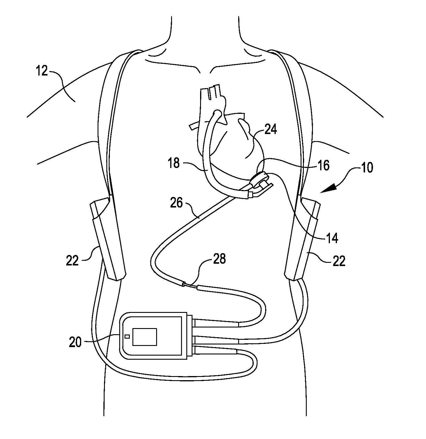
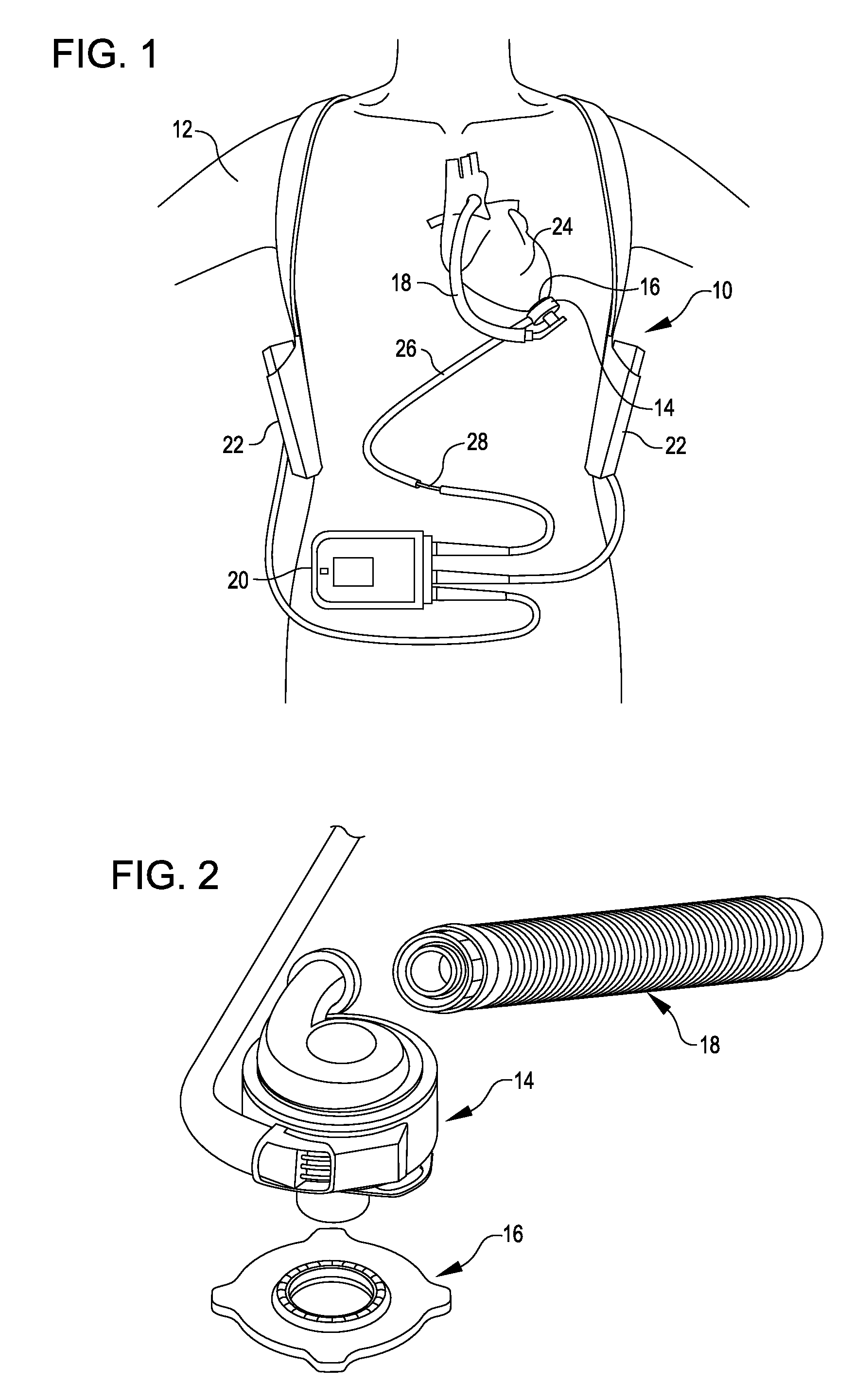
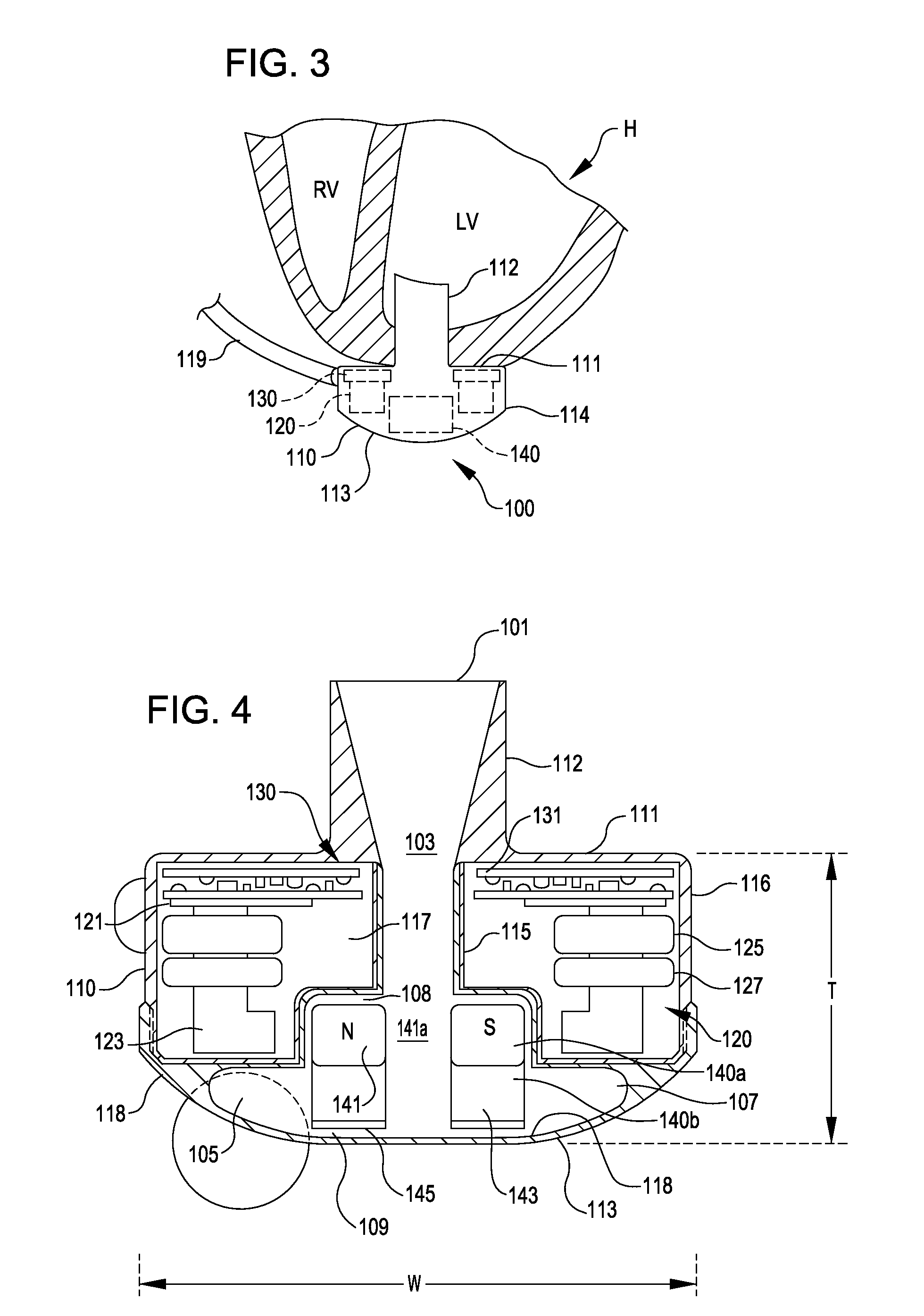
[0037]FIG. 1 is an illustration of a mechanical circulatory support system 10 implanted in a patient's body 12. The mechanical circulatory support system 10 comprises a implantable blood pump assembly 14, ventricular cuff 16, outflow cannula 18, an external system controller 20, and power sources 22. The implantable blood pump assembly 14 may comprise a VAD that is attached to an apex of the left ventricle, as illustrated, or the right ventricle, or both ventricles of the heart 24. The VAD may comprise a centrifugal (as shown) or axial flow pump as described in further detail herein that is capable of pumping the entire output delivered to the left ventricle from the pulmonary circulation (i.e., up to 10 liters per minute). Related blood pumps applicable to the present invention are described in greater detail below and in U.S. Pat. Nos. 5,695,471, 6,071,093, 6,116,862, 6,186,665, 6,234,772, 6,264,635, 6,688,861, 7,699,586, 7,976,271, 7,997,854, 8,007,254, 8,152,493, 8,652,024, and ...


PUM


Abstract

A method for outputting a combined power source alarm for an implantable blood pump includes determining a status for each of first and second power sources of the blood pump. A combined power source alarm based on the statuses of the first and second power sources is outputted. A method for generating an alarm based on fault detections in a mechanically assisted circulation system includes processing a series of fault detection indications to classify a fault as active or inactive. An alarm is generated if the fault is active for more than a predetermined amount of time.

Description

CROSS-REFERENCE TO RELATED APPLICATIONS[0001]This application claims the benefit of U.S. Provisional Application No. 61 / 979,845, filed Apr. 15, 2014, which is incorporated herein by reference in its entirety for all purposes.BACKGROUND[0002]This application relates generally to mechanically assisted circulation (MAC) systems, and more specifically relates to improved methods and systems for generating alarms based on fault detections in a MAC system. Such alarms can relate to an implantable blood pump of an MAC system as well as to power sources for the blood pump.[0003]Ventricular assist devices, known as VADs, are implantable blood pumps used for both short-term (i.e., days, months) and long-term applications (i.e., years or a lifetime) where a patient's heart is incapable of providing adequate circulation, commonly referred to as heart failure or congestive heart failure. According to the American Heart Association, more than five million Americans are living with heart failure, ...

Claims


Application Information

Patent Timeline
Patent Type & Authority Applications(United States)
IPC IPC(8): G08B21/18A61M60/178A61M60/216A61M60/422A61M60/538A61M60/585A61M60/814A61M60/82A61M60/857A61M60/863A61M60/88
CPCG08B21/182A61M60/148A61M60/82A61M60/857A61M60/422A61M60/88A61M60/863A61M60/216A61M60/178A61M60/538A61M60/814A61M60/585
Inventor KIMBALL, BRIANDAGUE, CHARLESWU, W. KEVIN
Owner TC1 LLC
Learn More