
System and method for non-contact optical-power measurement

a power measurement and non-contact technology, applied in the field of optical systems, can solve the problems power measurement without physical contact, etc., and achieve the effect of increasing the laser damage threshold of the optical fiber under tes

Active Publication Date: 2015-10-15
LOCKHEED MARTIN CORP
View PDF28 Cites 15 Cited by
  • Summary
  • Abstract
  • Description
  • Claims
  • Application Information

AI Technical Summary

Benefits of technology

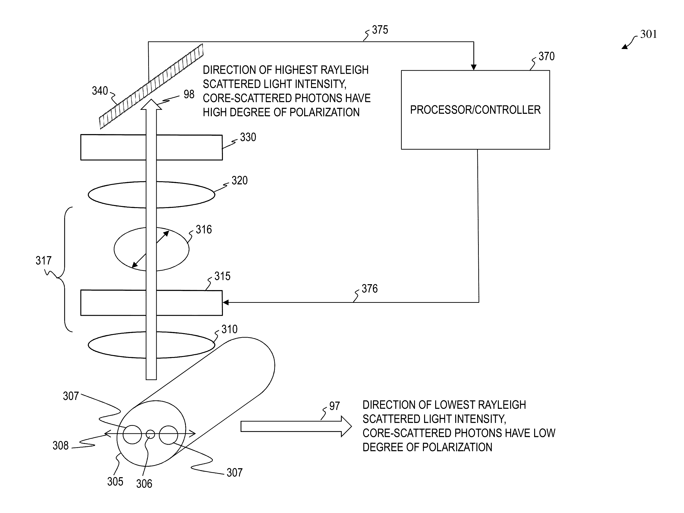
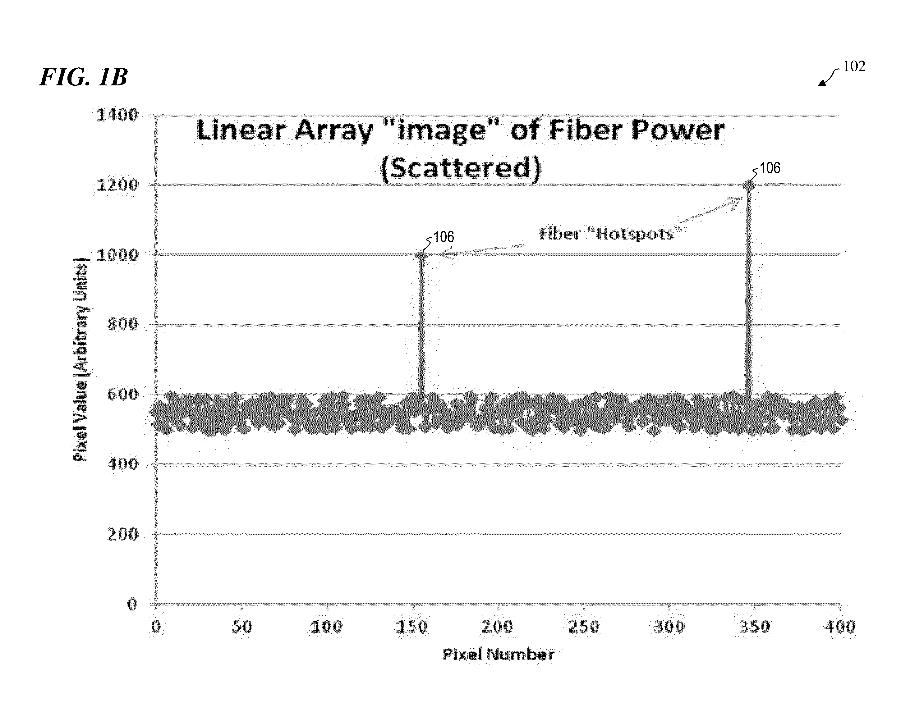
The present invention is a fiber-power-monitoring system that uses scattered energy from optical-fiber propagation without adding any throughput losses. It works by calculating the optical power propagating through the fiber without making any alterations to it. This system can handle both high-power and low-power levels and is suitable for both high-level and low-level applications. It includes optical components to discriminate scattered light from other sources, such as polarization filters, wavelength filters, and neutral density filters. Additionally, it includes components to improve calibration repeatability and accuracy, such as fiber loops and cladding dumps.

Problems solved by technology

In some embodiments, power measurement without physical contact increases the laser damage threshold of the optical fiber under test.

Method used


Image

  • System and method for non-contact optical-power measurement
  • System and method for non-contact optical-power measurement
  • System and method for non-contact optical-power measurement

Examples


Embodiment Construction

[0033]Although the following detailed description contains many specifics for the purpose of illustration, a person of ordinary skill in the art will appreciate that many variations and alterations to the following details are within the scope of the invention. Specific examples are used to illustrate particular embodiments; however, the invention described in the claims is not intended to be limited to only these examples, but rather includes the full scope of the attached claims. Accordingly, the following preferred embodiments of the invention are set forth without any loss of generality to, and without imposing limitations upon the claimed invention. Further, in the following detailed description of the preferred embodiments, reference is made to the accompanying drawings that form a part hereof, and in which are shown by way of illustration specific embodiments in which the invention may be practiced. It is understood that other embodiments may be utilized and structural change...


PUM

PropertyMeasurementUnit
poweraaaaaaaaaa
poweraaaaaaaaaa
poweraaaaaaaaaa

Abstract

The present invention provides methods and systems for measuring optical power that require neither alterations to the optical fiber nor physical contact with the optical fiber, the system including an optical fiber configured to propagate an optical signal, wherein the optical fiber includes a core and at least a first cladding layer, wherein a portion of the optical signal scatters out of the optical fiber along a length of the optical fiber to form scattered fiber light; a detector system configured to receive the scattered fiber light along the length of the optical fiber and to output a detection signal based on the received scattered fiber light; and a processor configured to receive the detection signal and to determine a power value of the optical signal based on the received detection signal.

Description

CROSS-REFERENCE TO RELATED APPLICATIONS[0001]This application claims priority benefit, under 35 U.S.C. §119(e), of U.S. Provisional Patent Application No. 61 / 978,736, filed Apr. 11, 2014 by Stephen J. Guimond, titled “SYSTEM AND METHOD FOR NON-CONTACT OPTICAL-POWER MEASUREMENT,” which is incorporated herein by reference in its entirety.[0002]This application is related to:U.S. Pat. No. 7,391,561 that issued Jun. 24, 2008 to Fabio Di Teodoro et al., titled “FIBER- OR ROD-BASED OPTICAL SOURCE FEATURING A LARGE-CORE, RARE-EARTH-DOPED PHOTONIC-CRYSTAL DEVICE FOR GENERATION OF HIGH-POWER PULSED RADIATION AND METHOD”;U.S. Pat. No. 7,570,856 that issued Aug. 4, 2009 to John D. Minelly et al., titled “APPARATUS AND METHOD FOR AN ERBIUM-DOPED FIBER FOR HIGH PEAK-POWER APPLICATIONS”;U.S. Pat. No. 7,768,700 that issued Aug. 3, 2010 to Matthias P. Savage-Leuchs, titled “METHOD AND APPARATUS FOR OPTICAL GAIN FIBER HAVING SEGMENTS OF DIFFERING CORE SIZES”;U.S. Pat. No. 7,876,803 that issued Jan. ...

Claims


Application Information

Patent Timeline
Patent Type & Authority Applications(United States)
IPC IPC(8): G01J1/02G01J1/04G02F1/01G02B6/036G02B6/028G01J1/42G02B6/024
CPCG01J1/0295G01J1/4228G01J1/0403G02F1/0136G02B6/03622G02B6/0283G02B6/024G01J1/4257G01J1/0429G01J1/0425G02B6/4216G02B6/4287G01M11/02
Inventor GUIMOND, STEPHEN J.
Owner LOCKHEED MARTIN CORP
Learn More