
Method and system for conformal imaging vibrometry

a technology of conformal fiberoptics and vibrometry, applied in the field of optics, can solve the problems of limitations of traditional modal analysis, limitations of such approaches, and the inference of global structural dynamic behavior further subject to additional restrictive assumptions

Active Publication Date: 2015-10-08
ADVANCED SYST & TECH
View PDF4 Cites 8 Cited by
  • Summary
  • Abstract
  • Description
  • Claims
  • Application Information

AI Technical Summary

Benefits of technology

The present invention provides a new method for analyzing the behavior of objects with any shape using a laser beam array. This approach allows for high-speed imaging of whole-body dynamics in real-time without the need for multiplexed data capture or synthesized motion reconstruction. The method measures the object's vibrations simultaneously at multiple points, enabling further characterization tests such as studying the effects of pressure and temperature variations on the object's dynamics. This new method uses heterodyne interferometry to encode the velocity of the vibrating surface in the Doppler sidebands of a frequency modulated carrier. The microprocessor recovers the displacement or velocity data by demodulating the measured, digitized signals to yield the local surface displacement or velocity time histories, which can be displayed in real-time to provide an animated display of the sample's surface deformation or velocity under transient stimulus.

Problems solved by technology

However, there are limitations with traditional modal analyses.
However, there are limitations with such approaches.
The inference of global structural dynamic behavior is further subject to additional restrictive assumptions concerning the actual structural behavior between sequentially scanned measurements.
In addition to the limitation of the restrictive assumptions implicit in traditional modal analyses, point measurements performed sequentially require application of repetitive stimulus for each point measurement, making this approach slow and unsuitable for the study of many system dynamics or diagnostic problems which entail transient, non-repetitive, complex (i.e., travelling wave) effects, or any combinations thereof.
Another limitation of the current state-of-the-art LDV is its inability to measure the vibratory motion of structures comprising convoluted or non-planar shapes, in particular where these are sufficiently small, reflective and / or delicate structures, such as micro-electromechanical sensors (MEMS).
However, such designs have the following limitations.
They are not capable of vibration imaging where “imaging” is taken to imply a sufficient number of simultaneous measurement points to resolve the smallest scale spatial vibrations of interest over a two-dimensional (“2D”) area.
Thus, such designs do not provide an imaging capability but instead employ, for example, a linear vibrometer array in conjunction with mechanical rotation or scanning to acquire 2D data.
Such approaches are thus susceptible to the same limitations of single point scanning systems as detailed previously.
The current state-of-the-art LDVs attempt to address the limitations of single beam measurements by providing a limited extension of LDV to spatially distributed measurements, but such approaches are not capable of vibration imaging and, in addition, are only applicable to planar or substantially planar surfaces and structures.
Thus, the current state-of-the-art LDV fails to provide simultaneous measurements of the real-time, full-field vibrometry motion of (i) structures with arbitrary geometry, and, in particular, structures with curved surfaces such as circular, cylindrical, spherical, or arbitrary curved two-dimensional or three-dimensional surfaces, and (ii) structures which exhibit rapid, abrupt or discontinuous variations of surface curvature.

Method used


Image

  • Method and system for conformal imaging vibrometry
  • Method and system for conformal imaging vibrometry
  • Method and system for conformal imaging vibrometry

Examples


Embodiment Construction

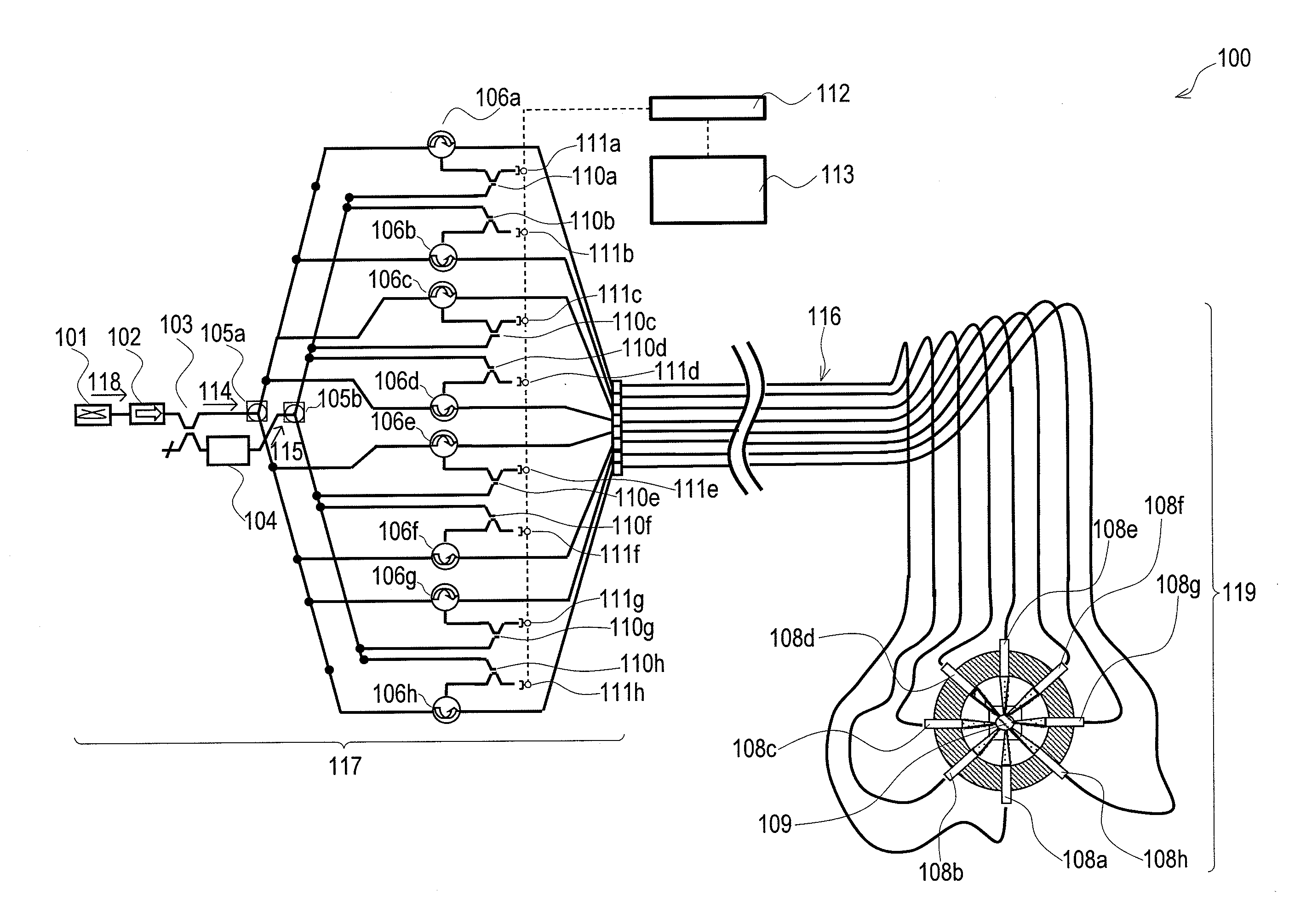
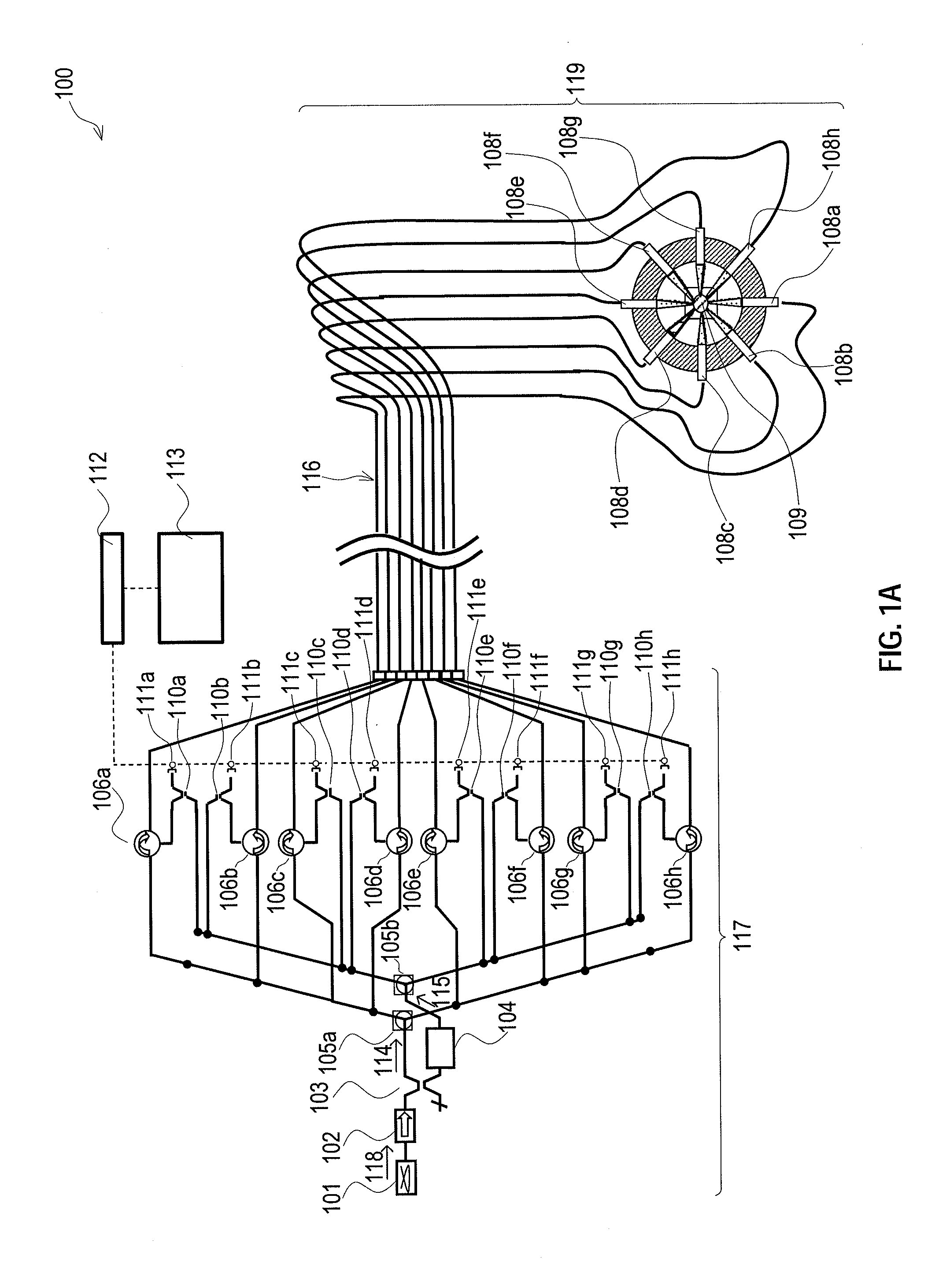
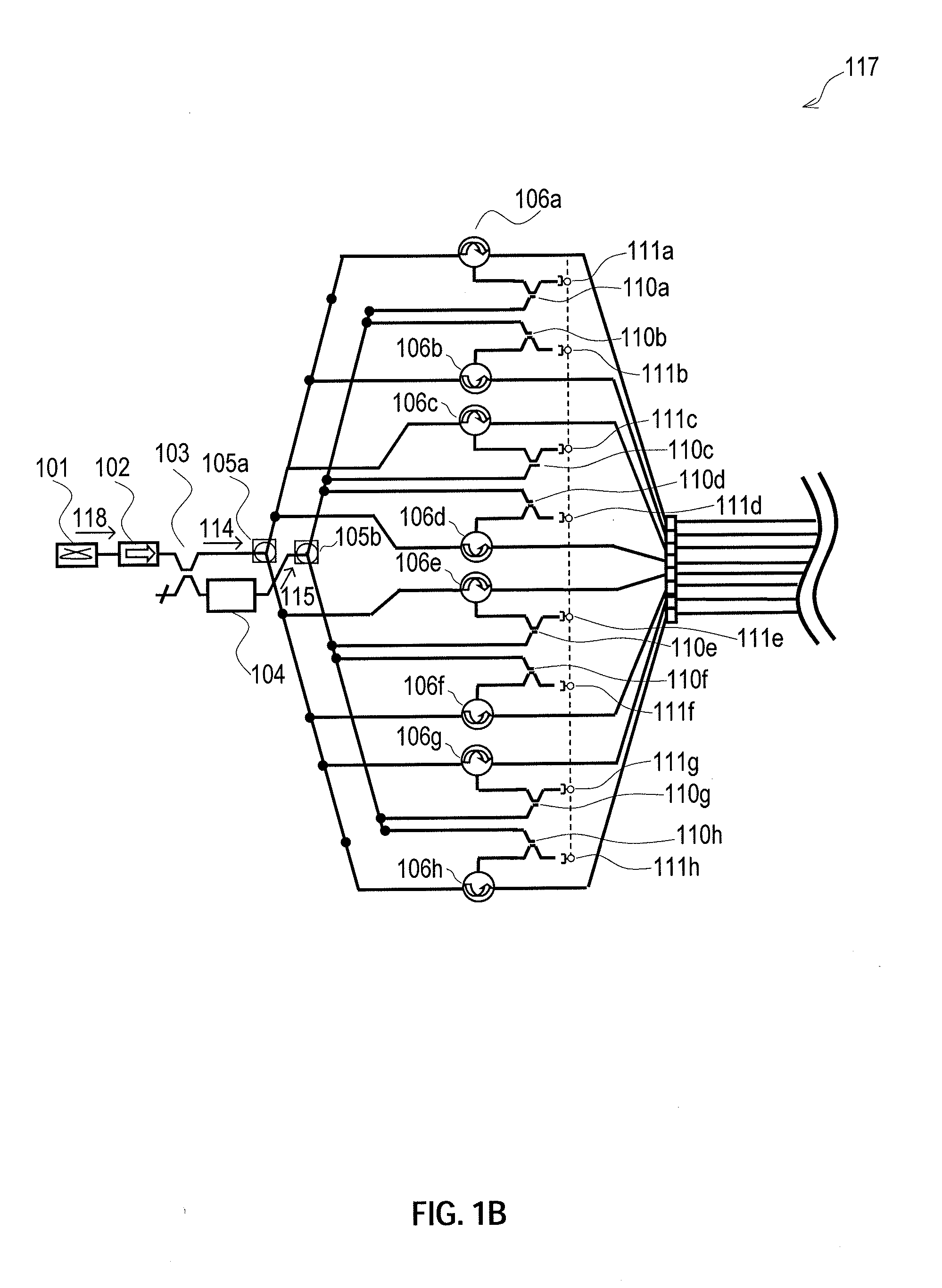
[0043]FIG. 1A is a schematic depicting an exemplary embodiment of the present invention's system for conformal imaging vibrometry capable of real-time measurements of the dynamic motions of any arbitrary two-dimensional or three-dimensional structure. The present invention's system represents a substantial departure from conventional bulk-optic vibrometer designs because it supports multi-channel configurations without significant impact on system size or complexity. The present invention's system achieves this outcome by incorporating fiber-optics component technology from the telecommunications field as part of an all-digital, multi-channel implementation of the traditional single-channel heterodyne vibrometer. Specifically, the present invention's system incorporates fiber-optics architecture from the laser source input to the receiver coupling scheme. The present invention's system uses active and passive fiber-optics components throughout to guarantee a robust optical alignment...


PUM


Abstract

Systems and methods for conformal imaging vibrometry capable of real-time measurements of the dynamic motions of any arbitrary two-dimensional or three-dimensional structure. The disclosed systems and methods are able to fully characterize the dynamic behavior of an object of any arbitrary geometry. The test object is illuminated with multiple laser beams whose directions conform to the local normal axis of the surface. The approach enables high-speed vibration imaging of whole-body dynamics of arbitrarily shaped structures in real-time, with no multiplexed data capture or synthesized motion reconstruction, as is currently practiced. By measuring the object's vibrations simultaneously at multiple points, the disclosed systems and methods are able to reproduce the structural behavior under operational conditions, which can then be spectrally decomposed to determine the modal, complex modal and transient nature of the true structural dynamics.

Description

CLAIM OF PRIORITY UNDER 35 U.S.C. §119(e)[0001]This application claims the benefit and priority of U.S. Provisional Patent Application No. 61 / 713,040, entitled “METHOD AND APPARATUS FOR CONFORMAL IMAGING VIBROMETRY,” filed on Oct. 12, 2012, the entire contents and disclosures of which are hereby incorporated by reference herein.STATEMENT REGARDING GOVERNMENT RIGHTS[0002]This invention was made with Government support under Contract Nos. N68335-11-C-0268, W31P4Q-11-C-0061, and W15P7T-13-C-A408, all awarded by the Army Contracting Command Office—APG on behalf of the Defense Advanced Research Projects Agency (“DARPA”), and the Naval Air Warfare Center Aircraft Division (“NAVAIR”). The Government has certain rights in this invention.BACKGROUND[0003]1. Field of the Invention[0004]The present invention relates generally to optics and more particularly, to conformal fiber-optics vibrometry for real-time full-field measurement of the displacement and vibration of arbitrarily-shaped surfaces...

Claims


Application Information

Patent Timeline
Patent Type & Authority Applications(United States)
IPC IPC(8): G01B9/02G01P3/36G01B11/14
CPCG01B9/02007G01B9/02041G01P3/36G01B11/14G01H9/00G01M7/025
Inventor KILPATRICK, JAMESAPOSTOL, ADELAMARKOV, VLADIMIR
Owner ADVANCED SYST & TECH
Learn More