Base station and associated method for assigning uplink resources to terminal devices with a similar traffic profile

a technology of uplink resources and terminal devices, applied in the field of wireless (mobile) telecommunications systems, can solve problems such as increased potential for network congestion and interferen

Active Publication Date: 2015-10-01
CONVIDA WIRELESS LLC
View PDF5 Cites 31 Cited by
  • Summary
  • Abstract
  • Description
  • Claims
  • Application Information

AI Technical Summary

Benefits of technology

[0033]In accordance with some embodiments the base station is configured such that the terminal device classifier is a quality class indicator of respective bearers associated with the respective terminal devices.
[0034]In accordance with some embodiments the controller unit is further configured to control the transceiver to transmit an access request denial message to the second terminal device to instruct the second terminal device not to make its own request for an allocation of radio resources.
[0035]In accordance with some embodiments the controller unit is further configured to control the transceiver to transmit a cease access request denial message to the second terminal device after having transmitted the access request denial message to instruct the second terminal device that it is now allowed to make its own request for an allocation of radio resources.
[0036]In accordance with some embodiments the controller unit is further configured to control the transceiver to transmit an access request allow message to the first terminal device to instruct the first terminal device that it is allowed to make the request for the allocation of radio resources.

Problems solved by technology

This desire to support more devices, however, gives rise to an increased potential for issues with network congestion and interference, particular in respect of the radio access interface.

Method used


Image

  • Base station and associated method for assigning uplink resources to terminal devices with a similar traffic profile
  • Base station and associated method for assigning uplink resources to terminal devices with a similar traffic profile
  • Base station and associated method for assigning uplink resources to terminal devices with a similar traffic profile

Examples


Embodiment Construction

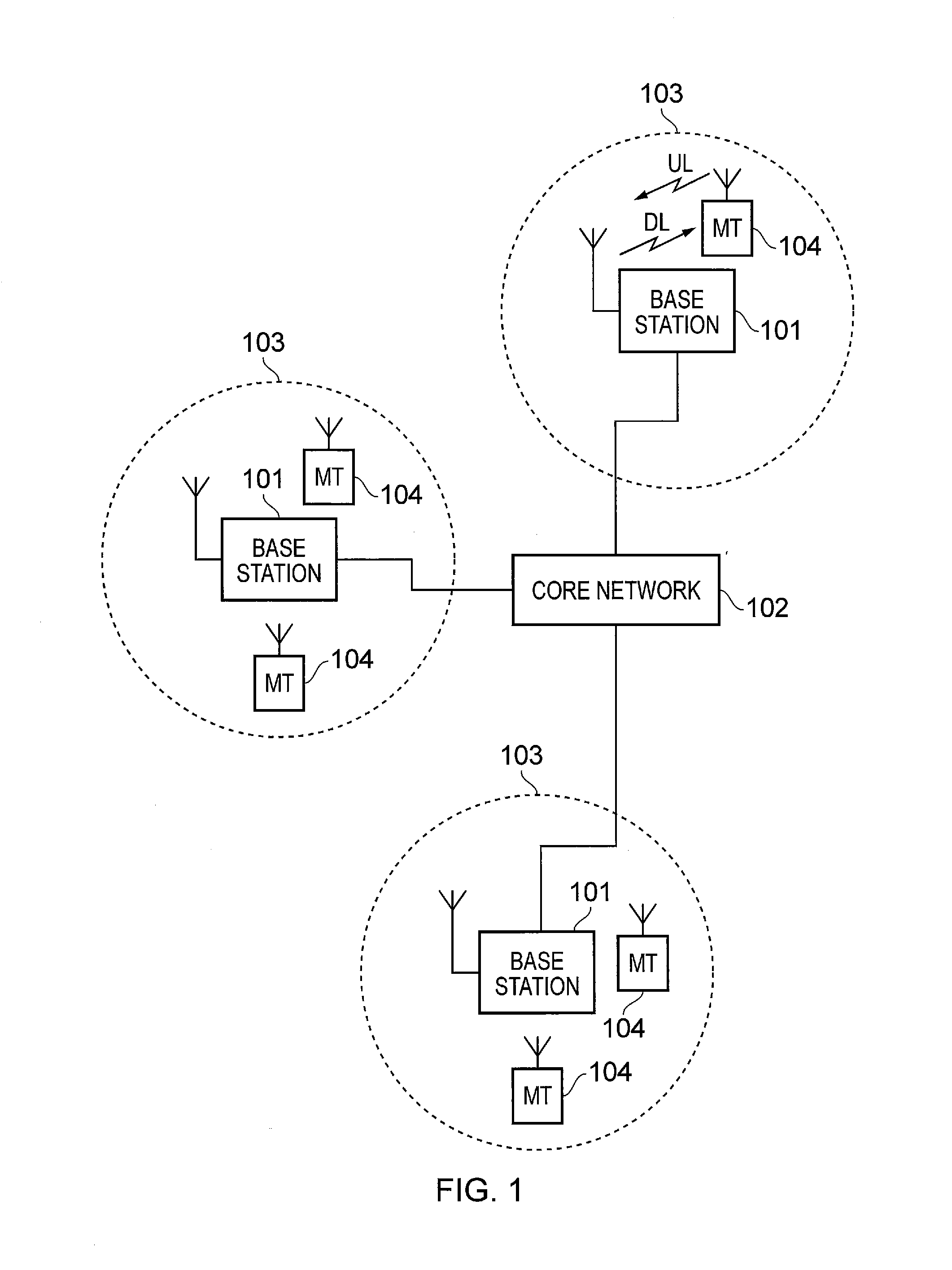
[0087]FIG. 1 provides a schematic diagram illustrating some basic functionality of a wireless telecommunications network / system 100 operating in accordance with LTE principles. Various elements of FIG. 1 and their respective modes of operation are well-known and defined in the relevant standards administered by the 3GPP® body and also described in many books on the subject, for example, Holma H. and Toskala A [2]. The network 100 includes a plurality of base stations 101 connected to a core network 102. Each base station provides a coverage area 103 (i.e. a cell) within which data can be communicated to and from terminal devices 104. Data is transmitted from base stations 101 to terminal devices 104 within their respective coverage areas 103 via a radio downlink. Data is transmitted from terminal devices 104 to the base stations 101 via a radio uplink. The radio downlink and radio uplink may together be considered to support the radio interface for the wireless telecommunications sy...


PUM


Abstract

A method of allocating radio resources for uplink transmissions in a wireless telecommunications system, including: a first terminal device communicating a request for an allocation of radio resources to a base station; the base station determining whether there is an association between the first terminal device and a second terminal device based on their having similar predicted traffic profiles for uplink data; and the base station establishing a radio resource allocation for the second terminal device based on the resources requested by the first terminal device, and consequently transmitting radio resource allocation messages to allocate radio resources to the first and the second terminal devices for respective uplink transmissions based on the request for an allocation of radio resources received from the first terminal device.

Description

BACKGROUND OF THE INVENTION[0001]The present invention relates to methods, systems and apparatus for use in wireless (mobile) telecommunications systems. In particular, embodiments of the invention relate to communicating uplink allocations of radio resources from a base station to a terminal device in such systems.[0002]Third and fourth generation mobile telecommunication systems, such as those based on the 3GPP defined UMTS and Long Term Evolution (LTE) architectures, are able to support more sophisticated services than simple voice and messaging services offered by previous generations of mobile telecommunication systems.[0003]For example, with the improved radio interface and enhanced data rates provided by LTE systems, a user is able to enjoy high data rate applications such as mobile video streaming and mobile video conferencing that would previously only have been available via a fixed line data connection. The demand to deploy third and fourth generation networks is therefor...

Claims


Application Information

Patent Timeline
Patent Type & Authority Applications(United States)
IPC IPC(8): H04W72/04H04W4/70
CPCH04W72/0453H04W72/048H04W72/121H04W74/006H04W4/70H04W48/12H04W72/23H04W72/51
Inventor WEBB, MATTHEWWAKABAYASHI, HIDEJI
Owner CONVIDA WIRELESS LLC
Why Eureka
Try Eureka