Raman microscope and electron microscope analytical system

an electron microscope and microscope technology, applied in the direction of material analysis, instruments, electrical equipment, etc., can solve the problems of slow adjustment, difficult to achieve the sample analysis at the same precise point in both microscopes, and disadvantage of continuing to set the incident point of light beam

Inactive Publication Date: 2015-10-01
TESCAN ORSAY HLDG AS +1
View PDF9 Cites 9 Cited by
  • Summary
  • Abstract
  • Description
  • Claims
  • Application Information

AI Technical Summary

Benefits of technology

[0009]In accordance with the present invention, there is provided a Raman microscope and electron microscope analytical system comprising a vacuum chamber, a chamber stage to support a sample in a vacuum chamber, an electron microscope having electron microscope optical axis for producing electron beam and directing it to the sample and a Raman microscope that comprises a spectroscopy system, a scattered light detector, an illumination source, a light beam forming optics and an optical objective lens having Raman microscope optical axis, said optical objective lens is configured to focus received light beam at the sample so as to create a light spot at the sample and induce scattered light, wherein said optical objective lens is connected to the objective manipulator that allows movement of the optical objective lens in at least first direction along the Raman microscope optical axis and second direction in a plane perpendicular to the Raman microscope optical axis.
[0012]In another embodiment, the analytical system further comprises the confocal means that reduce scattered light from non-desired planes out of the focal point.

Problems solved by technology

That yields several disadvantages, foremost the complicated and slow adjustment of the sample position making more difficult to achieve the sample analysis at the same precise point in both microscopes.
Both of these documents, together with those described above, leave the disadvantage of the necessity to continue setting the incident point of the light beam for Raman spectroscopic analysis by moving the sample stage.
This yields the disadvantage that behavior of the piezo-manipulator depends on a specimen weight which is more significant especially at higher speeds of the sample stage.
This disadvantage arises especially in Raman mapping of a specific area.
These instruments commonly reach the resolution of only 2 5 micrometers, which is incomparably worse than in typical stand-alone Raman microscopes.
Another disadvantage is much smaller field of view for the navigation on the sample than by using of the optical objective.
As the incident light beam needs to be defocussed for scanning, the light intensity impinging the analyzed point is significantly reduced and the low intensity of the scattered light worsens the analytical ability of this system.
There is a lower useful signal to noise ratio, a longer time needed for analysis and therefore, the system is not useful for some applications.
This maintains disadvantage to focus by the sample stage.
Another disadvantage of this system is the fact that the laser beam is directed out of the objective optical axis in the course of deflection and that increases the spherical aberration of the system.

Method used


Image

  • Raman microscope and electron microscope analytical system
  • Raman microscope and electron microscope analytical system
  • Raman microscope and electron microscope analytical system

Examples


Embodiment Construction

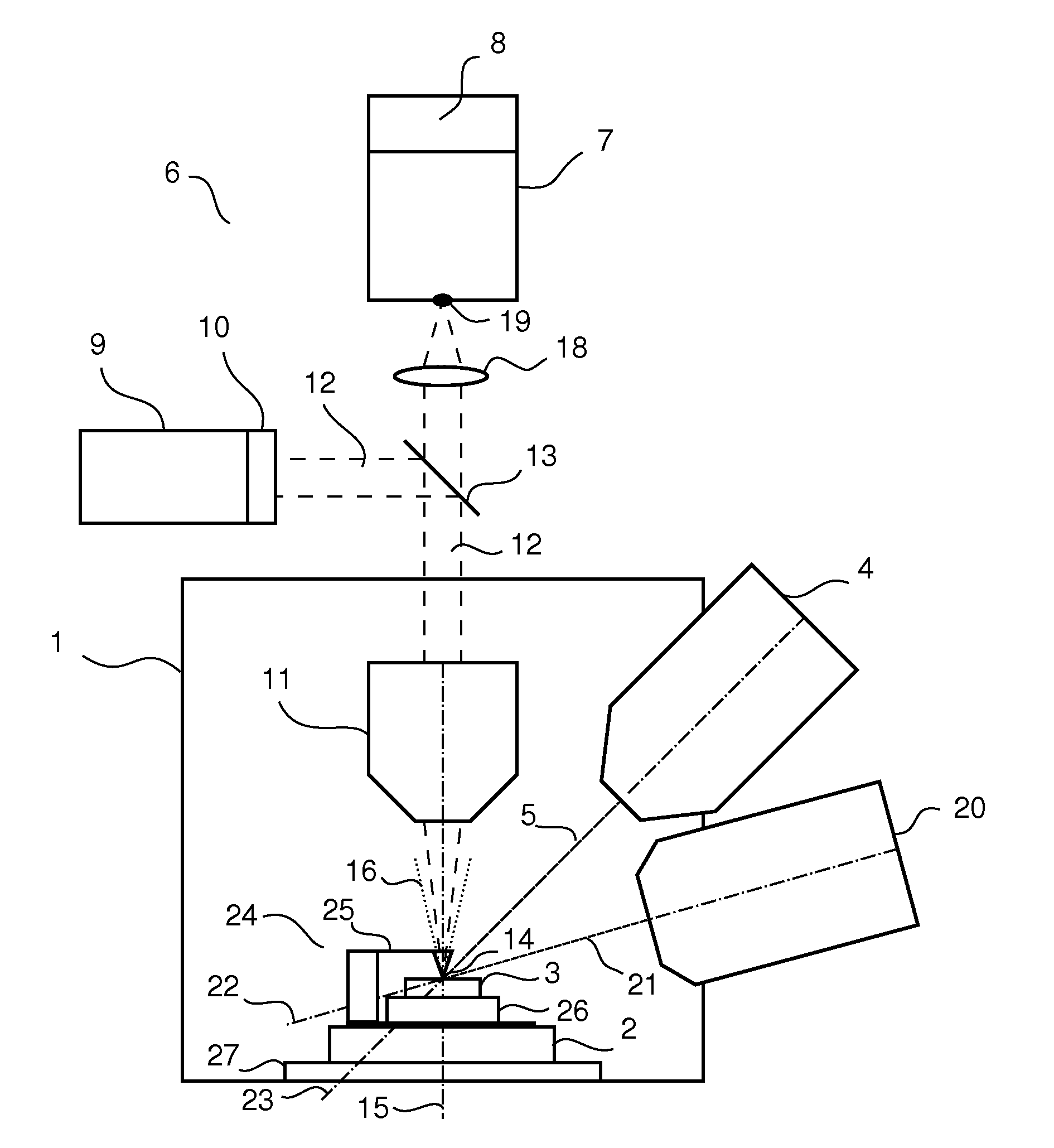
[0018]The example of preferred embodiment of the analytical system with Raman microscope and electron microscope is schematically drawn in FIG. 1. It comprises of a vacuum chamber 1 that serves for preserving of vacuum needed for function of the instruments using charged particles and it also forms the support for other system parts such as the chamber stage 2. The chamber stage 2 allows positioning of the sample 3 and is attached to vacuum chamber 1 by a movable stage manipulator 27. The stage manipulator 27 can function due to piezoelectric effect or can be actuated by a motor. The chamber stage 2 can be moved in all three axes and it also can turn around at least one axis. Besides supporting of the sample 3 can the stage manipulator 27 be used to position the sample 3 for analysis of certain point of sample 3 by some analytical instrument or also it can move the sample 3 to another analytical instrument. For those skilled in this area of technology, there are other ways to move t...


PUM

PropertyMeasurementUnit
Raman microscopeaaaaaaaaaa
electron microscopeaaaaaaaaaa
spectroscopyaaaaaaaaaa

Abstract

A system uses number of analytical devices such as an electron microscope a Raman microscope, an ion beam column and a scanning probe microscope for sample analysis concurrent, consecutive or with the mutual correlation of the analysis performed by the different devices in the same sample area using the connection of the Raman microscope optical objective lens and objective manipulator, that significantly reduces time needed for analyzing by Raman microscope together with other devices and maintains high quality of the sensed signals comparable to stand alone analytical devices.

Description

CROSS-REFERENCE TO RELATED APPLICATIONS[0001]This application claims priority to CZ Application No. PV 2014-184, filed on Mar. 26, 2014, the disclosure of which is incorporated herein by referenceFIELD OF THE INVENTION[0002]The submitted invention involves the system with Raman microscope and the electron microscope for analysis of specimen located in the vacuum chamber.BACKGROUND OF THE INVENTION[0003]The current applications of electron microscopes require continuously increasing analytical capabilities of the apparatus. The important data on the examined sample are obtained, for instance, by a method of diffraction back scattered electrons, by energy or wavelength-dispersive spectrometry but also by optical methods such as the Raman spectrometry. Thus, joining of Raman spectrometry and electron microscope, the simultaneous use of the high resolution of transmission electron microscope or scanning electron microscope, allow to analyze chemical compounds of the specific point of th...

Claims


Application Information

Patent Timeline
Patent Type & Authority Applications(United States)
IPC IPC(8): H01J37/28G01Q30/02H01J37/18G01N21/65H01J37/20G01N23/2251
CPCH01J37/28G01N21/65H01J37/20H01J37/18G01Q30/025G01N2201/061H01J2237/08H01J2237/2802H01J2237/2801H01J2237/2448H01J2237/24475H01J2237/063G01N2201/068G01J3/44H01J37/226H01J37/228H01J37/26H01J2237/024H01J2237/2583
Inventor JIRUSE, JAROSLAVHOLLRICHER, OLAFHANICINEC, MARTIN
Owner TESCAN ORSAY HLDG AS
Why Eureka
Try Eureka