
Surgical visualization system

Active Publication Date: 2015-10-01
CAMPLEX
View PDF87 Cites 173 Cited by
  • Summary
  • Abstract
  • Description
  • Claims
  • Application Information

AI Technical Summary

Benefits of technology

The patent describes a surgical retractor with cameras that can be used to provide access to a surgical site and track the location of the cameras. The cameras can be disposed on the retractor blades or the inside surface of a tube. The retractor can be used in spine surgery, head or neck surgery, or neurosurgery. The system can also include multiple cameras and tracking devices to provide a more comprehensive view of the surgical site. The technical effects of the patent include improved visualization for surgical procedures and improved access to surgical tools.

Problems solved by technology

Open surgery is associated with significant drawbacks, however, as the relatively large incisions result in pain, scarring, and the risk of infection as well as extended recovery time.
However, because of the small access opening, the surgeon's view and workspace of the surgical site is limited.

Method used


Image

  • Surgical visualization system
  • Surgical visualization system
  • Surgical visualization system

Examples


Embodiment Construction

[0182]The following description is directed to certain embodiments for the purposes of describing the innovative aspects of this disclosure. However, a person having ordinary skill in the art will readily recognize that the teachings herein can be applied in a multitude of different ways. The described embodiments may be implemented in any device or system that can be configured to provide visualization of a surgical site. Thus, the teachings are not intended to be limited to the embodiments depicted solely in the figures. and described herein, but instead have wide applicability as will be readily apparent to one having ordinary skill in the art.

Surgical Field Visualization

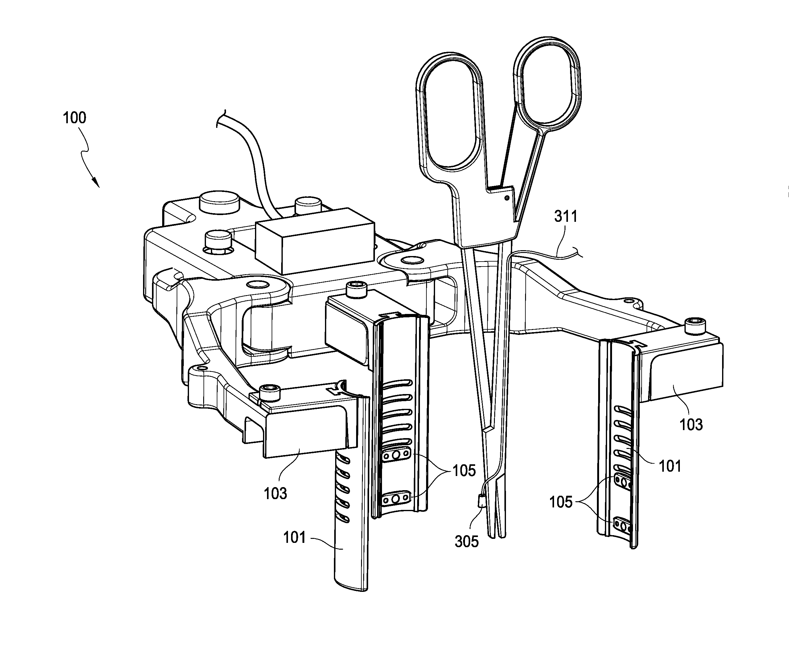
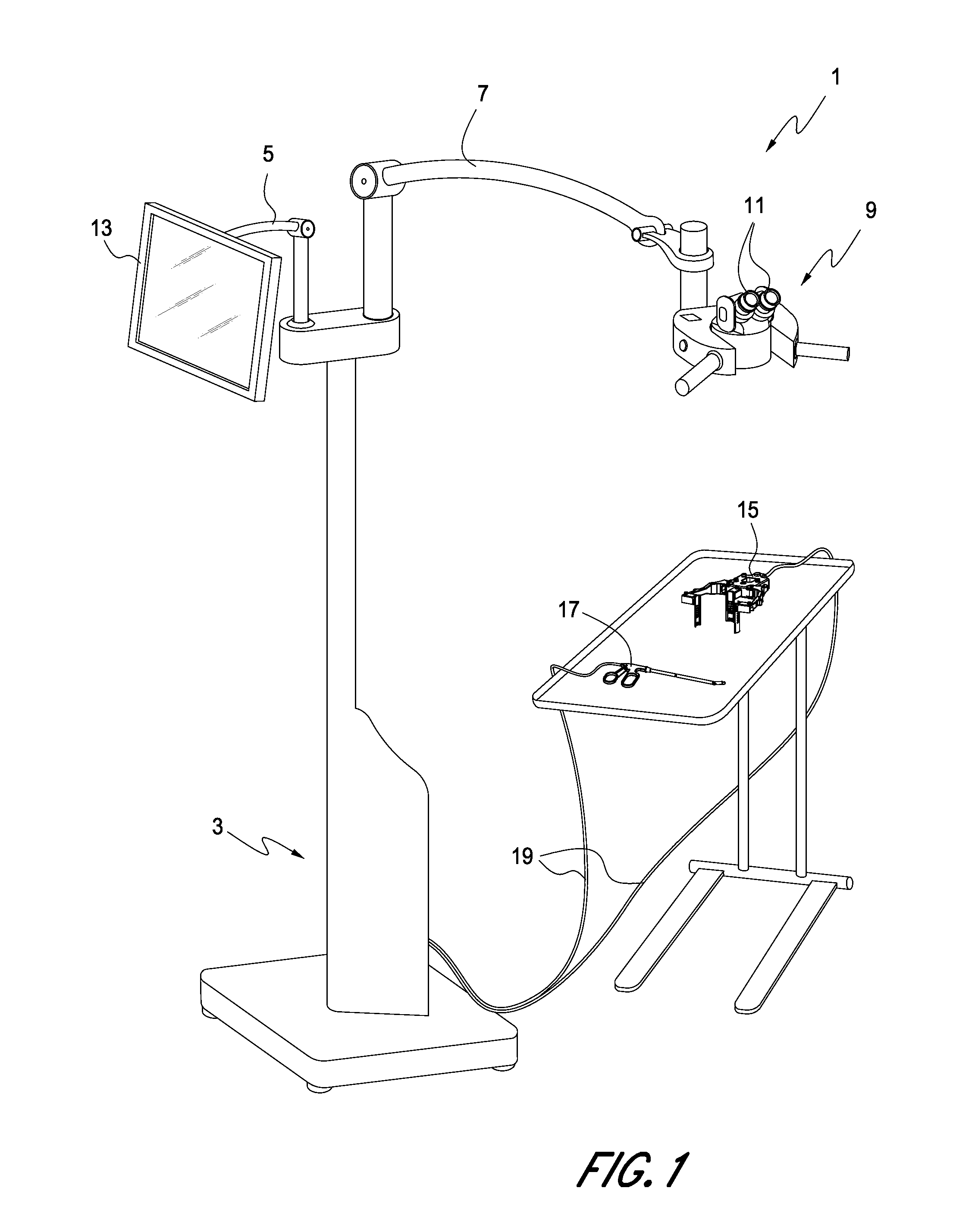
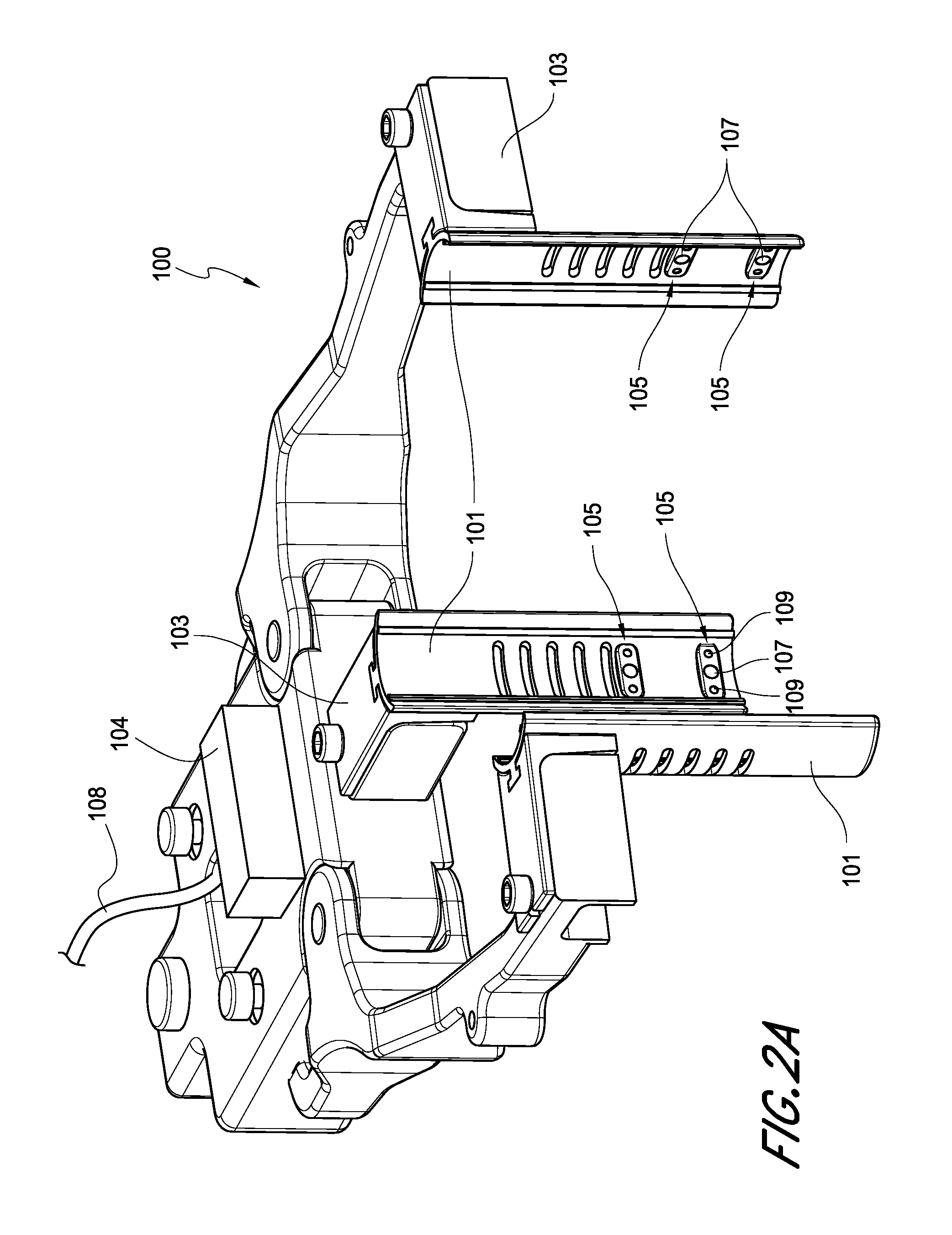
[0183]In order to provide for improved visualization of the surgical site, a surgical device can be provided with multiple cameras integrated therein. For example, the surgical device can be a retractor, and a plurality of cameras may be mounted on or within the retractor. In other embodiments, the surgical devic...


PUM


Abstract

A surgical device includes a plurality of cameras integrated therein. The view of each of the plurality of cameras can be integrated together to provide a composite image. A surgical tool that includes an integrated camera may be used in conjunction with the surgical device. The image produced by the camera integrated with the surgical tool may be associated with the composite image generated by the plurality of cameras integrated in the surgical device. The position and orientation of the cameras and / or the surgical tool can be tracked, and the surgical tool can be rendered as transparent on the composite image. A surgical device may be powered by a hydraulic system, thereby reducing electromagnetic interference with tracking devices.

Description

CROSS-REFERENCE TO RELATED APPLICATIONS[0001]This application is claims the benefit of priority of U.S. Provisional Application No. 61 / 803,371, filed Mar. 19, 2013. This application is also related to U.S. Provisional Application No. 61 / 665,243, filed Jun. 27, 2012, U.S. Provisional Application No. 61 / 670,550, filed Jul. 11, 2012, U.S. Provisional Application No. 61 / 703,727, filed Sep. 20, 2012, and U.S. Provisional Application No. 61 / 753,398, filed Jan. 16, 2013. Each of the above applications is hereby incorporated by reference in its entirety.BACKGROUND[0002]1. Field[0003]Embodiments of the present disclosure relate to surgical devices and visualization systems for use during surgery.[0004]2. Description of Related Art[0005]Some surgical operations involve the use of large incisions. These open surgical procedures provide ready access for surgical instruments and the hand or hands of the surgeon, allowing the user to visually observe and work in the surgical site, either directly...

Claims


Application Information

Patent Timeline
IPC IPC(8): A61B19/00A61B1/313A61B1/267A61B1/32A61B18/20
CPCA61B19/5212A61B1/32A61B18/20A61B19/5225A61B2560/0462A61B1/3132A61B2018/00982A61B2019/5227A61B2576/00A61B1/267A61B90/361A61B90/98A61B90/37A61B2090/371A61B2034/2051G16H40/63G16H20/40A61B17/02
Inventor CHARLES, STEVEN T.
Owner CAMPLEX
Learn More