Airfoil attachment holding an airfoil root in a broach fitting

a broach fitting and airfoil technology, applied in the direction of rotors, marine propulsion, vessel construction, etc., can solve the problems of more expensive design and more difficult to apply appropriately, and achieve the effect of reducing the simultaneous occurrence of damage in each portion and different stiffness

Active Publication Date: 2014-08-12
SN DETUDE & DE CONSTR DE MOTEURS DAVIATION S N E C M A
View PDF10 Cites 5 Cited by
  • Summary
  • Abstract
  • Description
  • Claims
  • Application Information

AI Technical Summary

Benefits of technology

[0010]According to one remarkable characteristic, the portions may have different stiffnesses obtained either by using different thicknesses or stiffeners such as ribs and particularly attachment tabs of a platform covering the attachment; the simultaneous occurrence of damage in each portion is thus reduced.

Problems solved by technology

The first safe-life design has the disadvantage that its design is more expensive because it is important to guard against more numerous or more restrictive conditions.
The second fail-safe design is preferred in this case, but it is also more difficult to apply appropriately in some circumstances, for example when the airfoil and its attachment are parts made of different materials made in a single piece assembly for which the strength is uncertain, because their connection depends partly on a bond.

Method used


Image

  • Airfoil attachment holding an airfoil root in a broach fitting
  • Airfoil attachment holding an airfoil root in a broach fitting
  • Airfoil attachment holding an airfoil root in a broach fitting

Examples


Embodiment Construction

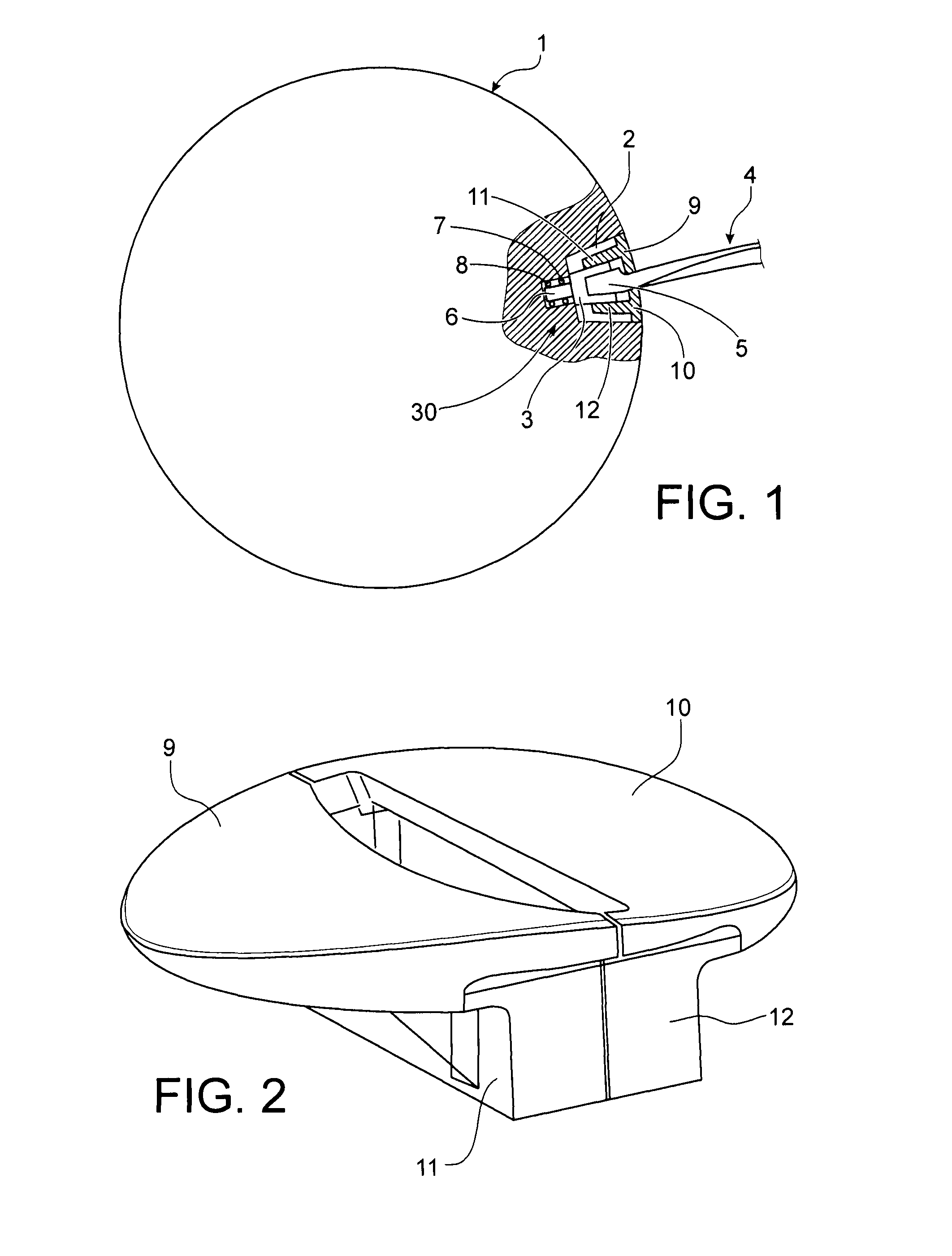
[0018]FIG. 1 shows an overview of a propeller. It comprises a hub (1) in which housings (2) are machined in a circular row. The housings (2) hold a pivoting attachment (3) of an airfoil (4). A root (5) of the airfoil (4) is held in the attachment (30), and the remainder of the airfoil (4) extends outside the hub (1). The root (5) is wider than the remainder of the airfoil (4). The airfoil (4) may be made of a composite material, while the attachment (30) is metallic. A pin (6) of the support is held in place by ball bearings (7 and 8) or by other bearings formed in the bottom of the housing (2) and that pivots it by entraining the airfoil (4), the pitch of which is modified. The pivoting device in the attachment (30) does not form part of the invention and therefore is not shown. Two platforms (9 and 10), fixed to the support (3) by ribs (11 and 12) facing the inside of the compartment, cover the housing (2) to create a smooth surface on the hub (1) and extend on each side of the ai...


PUM


Abstract

An airfoil attachment including a support and flanks rising on it to delimit a broach compartment designed to receive and hold an airfoil root is provided. The flanks are machined so as to separate the portions and prevent a complete break of a flank and detachment of the airfoil when a crack develops because the crack is stopped by one of the notches.

Description

BACKGROUND OF THE INVENTION[0001]1. Field of the Invention[0002]The subject of the invention is an airfoil attachment holding an airfoil root in a broach fitting.[0003]2. Description of the Related Art[0004]This attachment can be used for usually metallic supports of composite airfoils, and more particularly for devices for which the airfoils have a variable pitch, in other words their inclination relative to the rotation direction varies depending on the actual speed so as to improve the aerodynamic performances and efficiency of the engine to which they belong.[0005]The strength of the assembly between the airfoil and its attachment must be respected to prevent any risk of detachment of an airfoil during operation, with an extremely high kinetic energy that can cause corresponding damage in the adjacent parts of the aircraft. A satisfactory attachment may satisfy one of two designs; in a first design, the attachment is designed to resist all loads that are normally applied to it; ...

Claims


Application Information

Patent Timeline
Patent Type & Authority Patents(United States)
IPC IPC(8): B64C11/06
CPCB64C11/06
Inventor FABRE, ADRIEN JACQUES PHILIPPEMAHIEU, JEAN-NOELMARSAL, DAVID
Owner SN DETUDE & DE CONSTR DE MOTEURS DAVIATION S N E C M A
Why Eureka
Try Eureka