
Method and apparatus for sealing an undesirable formation zone in the wall of a wellbore

a formation zone and wellbore technology, applied in the direction of sealing/packing, wellbore/well accessories, fluid removal, etc., can solve the problems of reducing the natural ability of a reservoir to produce its fluid, reducing the formation permeability plugging damage, and difficult to repair, so as to achieve sufficient elasticity for operation and minimize drag

Active Publication Date: 2015-09-24
SAUDI ARABIAN OIL CO
View PDF4 Cites 63 Cited by
  • Summary
  • Abstract
  • Description
  • Claims
  • Application Information

AI Technical Summary

Benefits of technology

The patent describes a way to stop a problem water zone in an oil well by intentionally damaging the formation. This method uses coiled tubing instead of a rig, which saves money. It maintains the benefits of producing oil from the open hole instead of perforations in cemented casing.

Problems solved by technology

The possibility of causing formation permeability plugging damage exists during operations throughout the life of the well.
Wellbore damage can cause a reduction in the natural capability of a reservoir to produce its fluids, such as a decrease in porosity or permeability, or both.
Damage can occur near the wellbore face which can be relatively easy to repair or deep into the rock which may be difficult to repair.
Damage can occur when sensitive formations are exposed to drilling fluids.
Natural damage occurs as produced reservoir fluids move through the reservoir, while induced damage is the result of external operations and fluids in the well, such as drilling, well completion, workover operations or stimulation treatments.
Some induced damage triggers natural damage mechanisms.
In general, formation plugging is considered to be an undesirable phenomenon.

Method used


Image

  • Method and apparatus for sealing an undesirable formation zone in the wall of a wellbore
  • Method and apparatus for sealing an undesirable formation zone in the wall of a wellbore
  • Method and apparatus for sealing an undesirable formation zone in the wall of a wellbore

Examples


Embodiment Construction

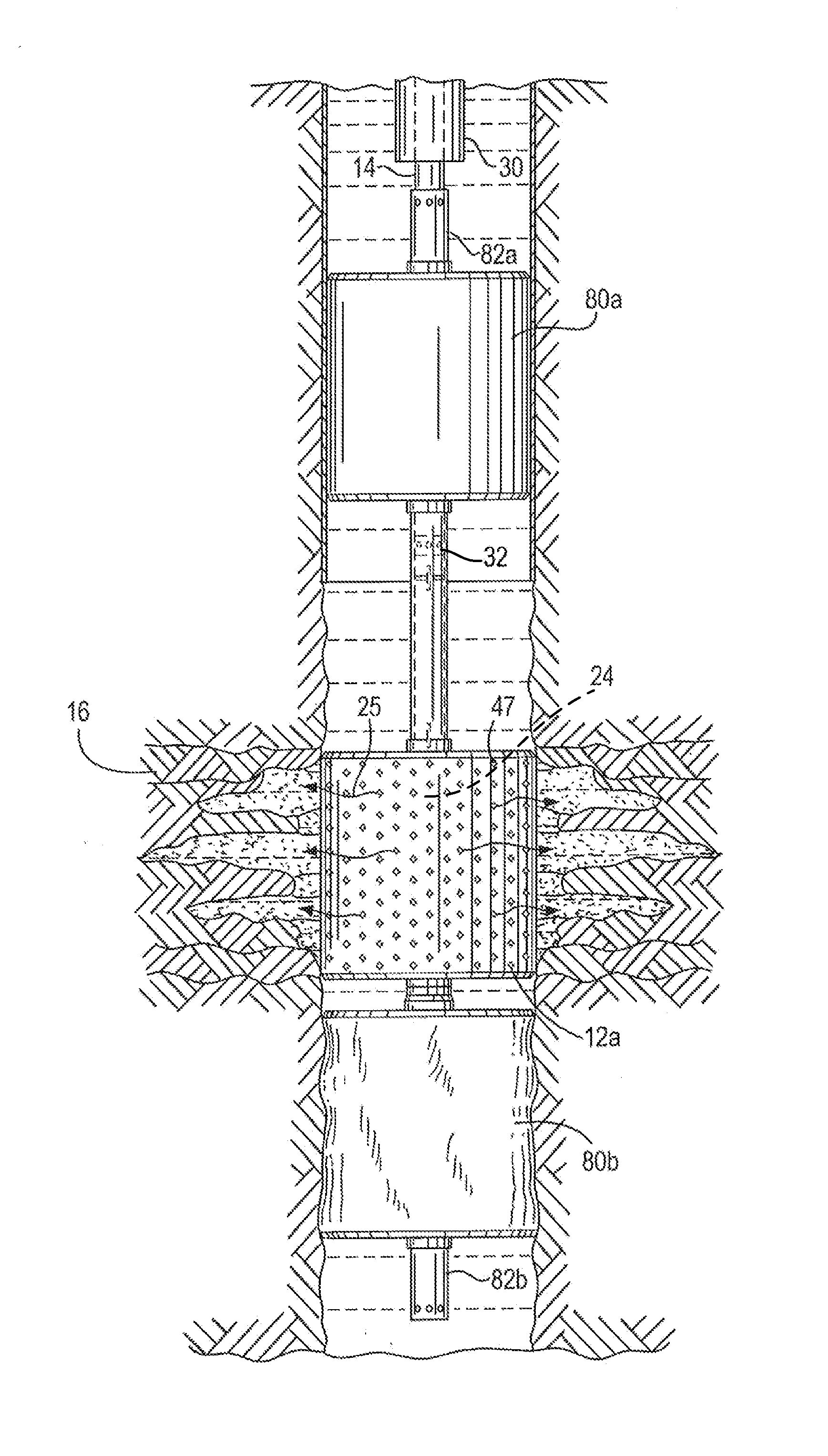
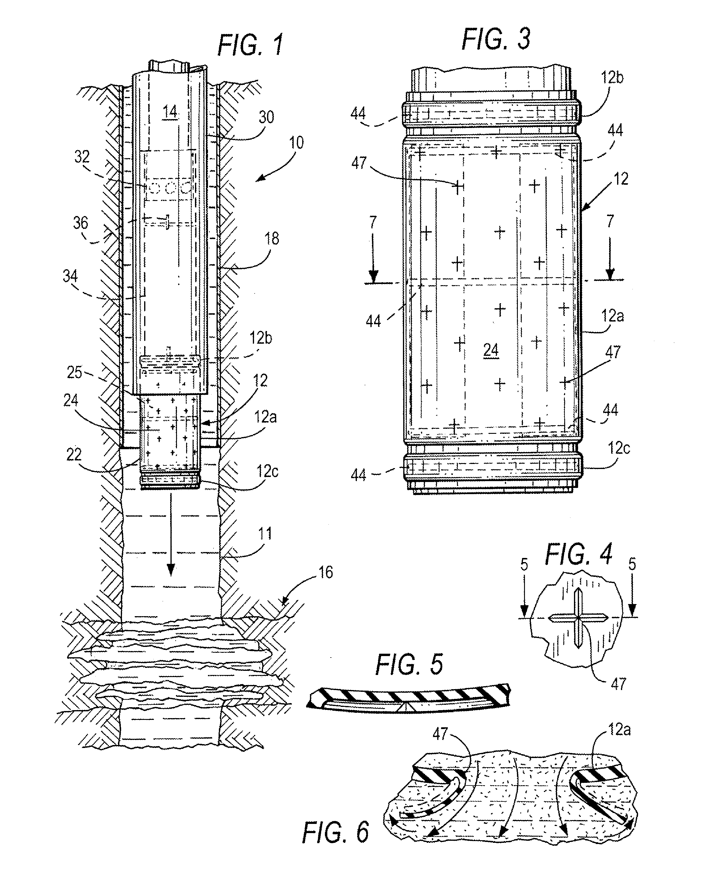
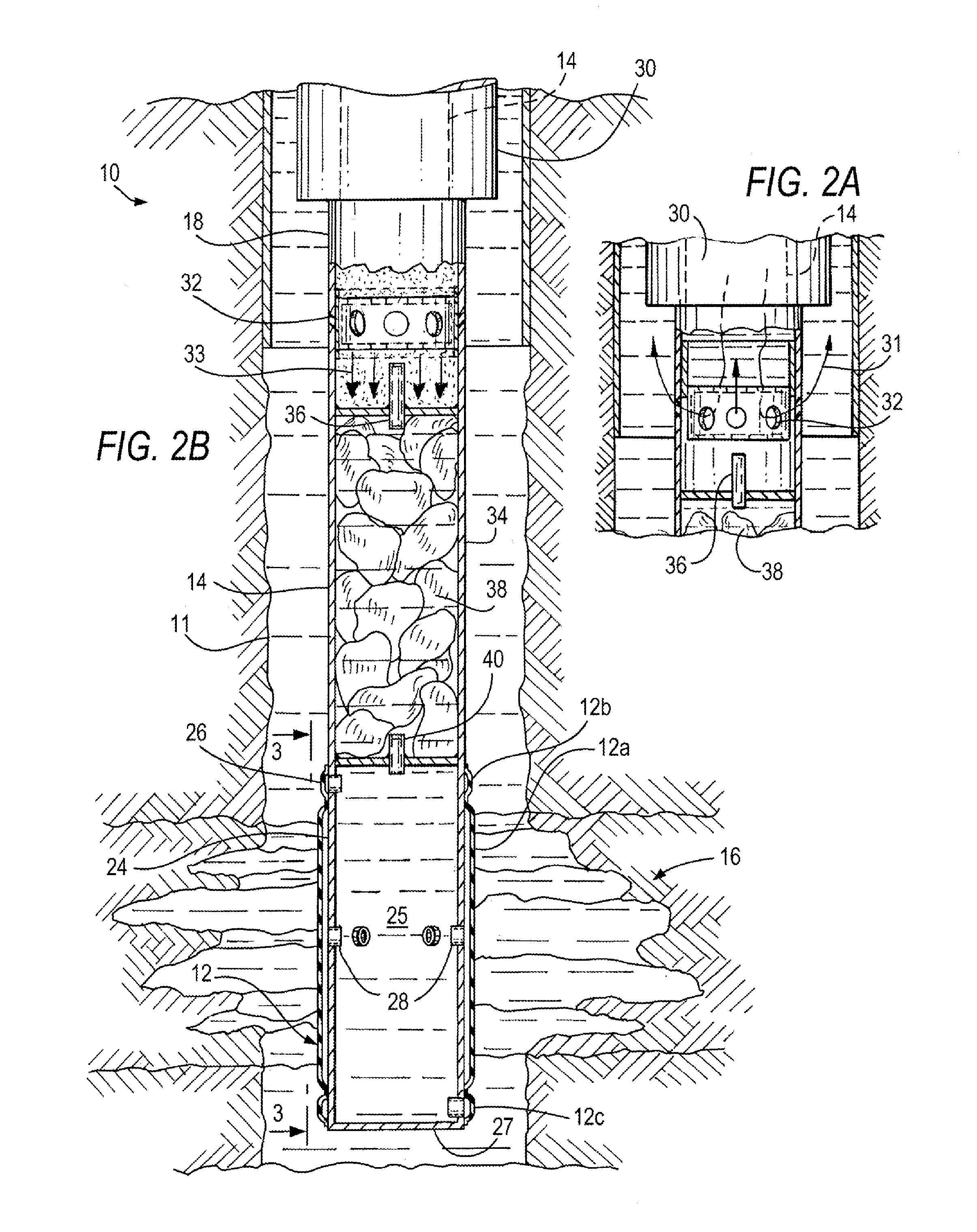
[0072]Referring now to the drawings, and specifically to FIG. 1, there is shown in elevation and partially in cross-section, an apparatus 10 constructed according to one embodiment of the present invention. The apparatus includes a resilient inflatable component, referred to generally as balloon 12, which is comprised of a plurality of sections and, as illustrated, of three sections, there being a central section 12a, referred to as the main or middle, or central balloon, an upper balloon 12b, and a lower balloon 12c. In the description which follows, reference to balloon 12 contemplates the balloon in its entirety, including the three sections, 12a, 12b and 12c, where balloon 12a is the central or middle balloon. The three sections are inflated according to a predetermined sequence as will be described in greater detail below.

[0073]The un-inflated balloon 12 and related components described below are deployed in the wellbore 11 by coiled tubing 14 which passes through production tu...


PUM


Abstract

A method and apparatus are provided for intentionally inducing “formation plugging” in a partially damaged section, water layer, or an otherwise undesirable target zone in the wall of a wellbore. The rigless apparatus is deployed to the target zone by coiled tubing and includes a pair of adjacent inflatable packers or a multi-section inflatable thermoplastic balloon component which is in valved fluid communication with an inflating container filled with formation plugging fluid. The inflating container is in valved fluid communication with a reactant-filled chemical container, the reactant being activated by contact with reactant fluid pumped through the coiled tubing via a circulation valve. The hot pressurized exothermic reaction products pass into the inflation container and displace the formation plugging fluid into the balloon sections and through weakened portions of a central balloon to penetrate the walls of the target zone. The expanded central balloon is melted by the heat of the chemical reaction and a portion adheres to the formation wall thereby sealing the undesirable target zone; thereafter, the remaining balloon sections are deflated or ruptured to permit the apparatus to be withdrawn through the production tubing.

Description

BACKGROUND OF THE INVENTION[0001]1. Field of the Invention[0002]The present invention relates to the intentional inducement of downhole formation damage in a target zone to produce deep plugging of the formation matrix and sealing the zone at the wellbore face.[0003]2. Description of the Related Art[0004]Prediction of formation plugging damage that occurs while drilling wells is an important factor in optimizing an oil field's development. The economic impact of near-wellbore drilling-induced damage and cleanup efficiency has led to significant progress in both experimental and numerical studies in order to assess wellbore flow properties during oil production.[0005]The possibility of causing formation permeability plugging damage exists during operations throughout the life of the well. Wellbore damage can cause a reduction in the natural capability of a reservoir to produce its fluids, such as a decrease in porosity or permeability, or both. Damage can occur near the wellbore face...

Claims


Application Information

Patent Timeline
Patent Type & Authority Applications(United States)
IPC IPC(8): E21B33/127E21B34/10E21B23/06
CPCE21B33/1272E21B34/10E21B23/065E21B33/12E21B33/127E21B33/138
Inventor AL-GOUHI, WALEED ABDULLAH
Owner SAUDI ARABIAN OIL CO
Learn More