Machining jig for rotatably supporting workpiece with respect to tool of machine tool and machining system

a technology of machining system and workpiece, which is applied in the direction of manufacturing tools, metal-working machine components, work transfer apparatus, etc., can solve the problems of affecting the ejection of machined workpieces by robots or loaders or other automatic devices, inability to eject machined workpieces, and damage to the top surface of workpieces

Active Publication Date: 2015-09-24
FANUC LTD
View PDF6 Cites 7 Cited by
  • Summary
  • Abstract
  • Description
  • Claims
  • Application Information

AI Technical Summary

Benefits of technology

[0009]According to a third aspect of the present invention, there is provided a machining system comprising: a machine tool which has a machining jig according to the first or second aspect, a control device which generate an operational command for the machine tool based on a predetermined machining program, a measuring device which measures a position of a workpiece which is p...

Problems solved by technology

However, the projection of the support table in the machine tool of JP-A-2011-513077 is sized so as to be tightly fitted into the center hole of a workpiece, and therefore it is difficult to eject a machined workpiece by a robot or loader or other automatic device.
Further, according to the machine tool of JP-A-2011-513077, positioning error of the cylinder or other drive device for driving the opposing holder causes the workpiece to be held in a state where the center hole of the workpiece is not concentric with the projection of the opposing holder.
Due to this, the inlet part of the...

Method used


Image

  • Machining jig for rotatably supporting workpiece with respect to tool of machine tool and machining system
  • Machining jig for rotatably supporting workpiece with respect to tool of machine tool and machining system
  • Machining jig for rotatably supporting workpiece with respect to tool of machine tool and machining system

Examples


Embodiment Construction

[0021]Below, embodiments of the present invention will be explained in detail with reference to the drawings. Note that the following explanation does not limit the technical scope of the inventions which are described in the claims or the meaning of terms etc.

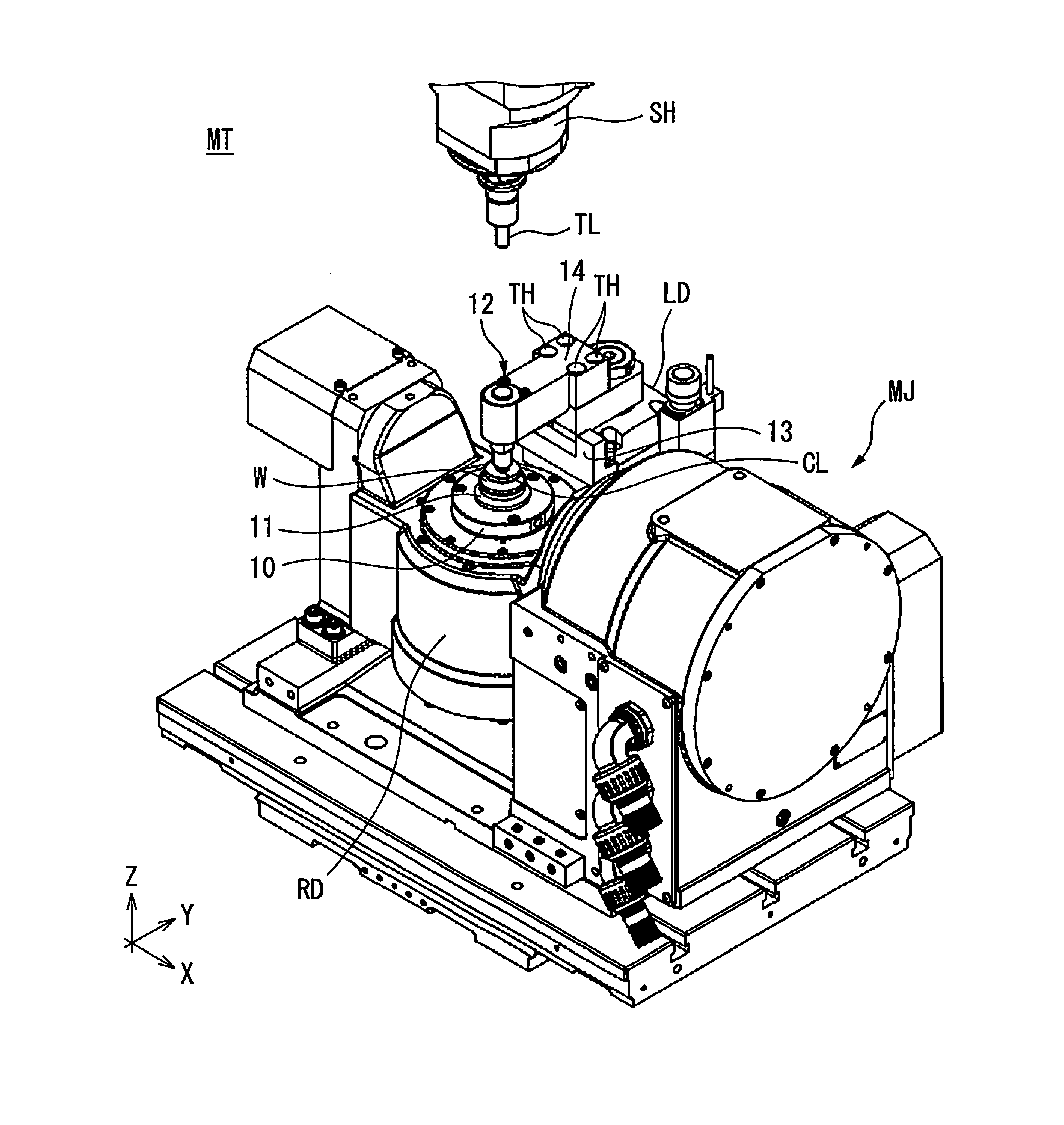
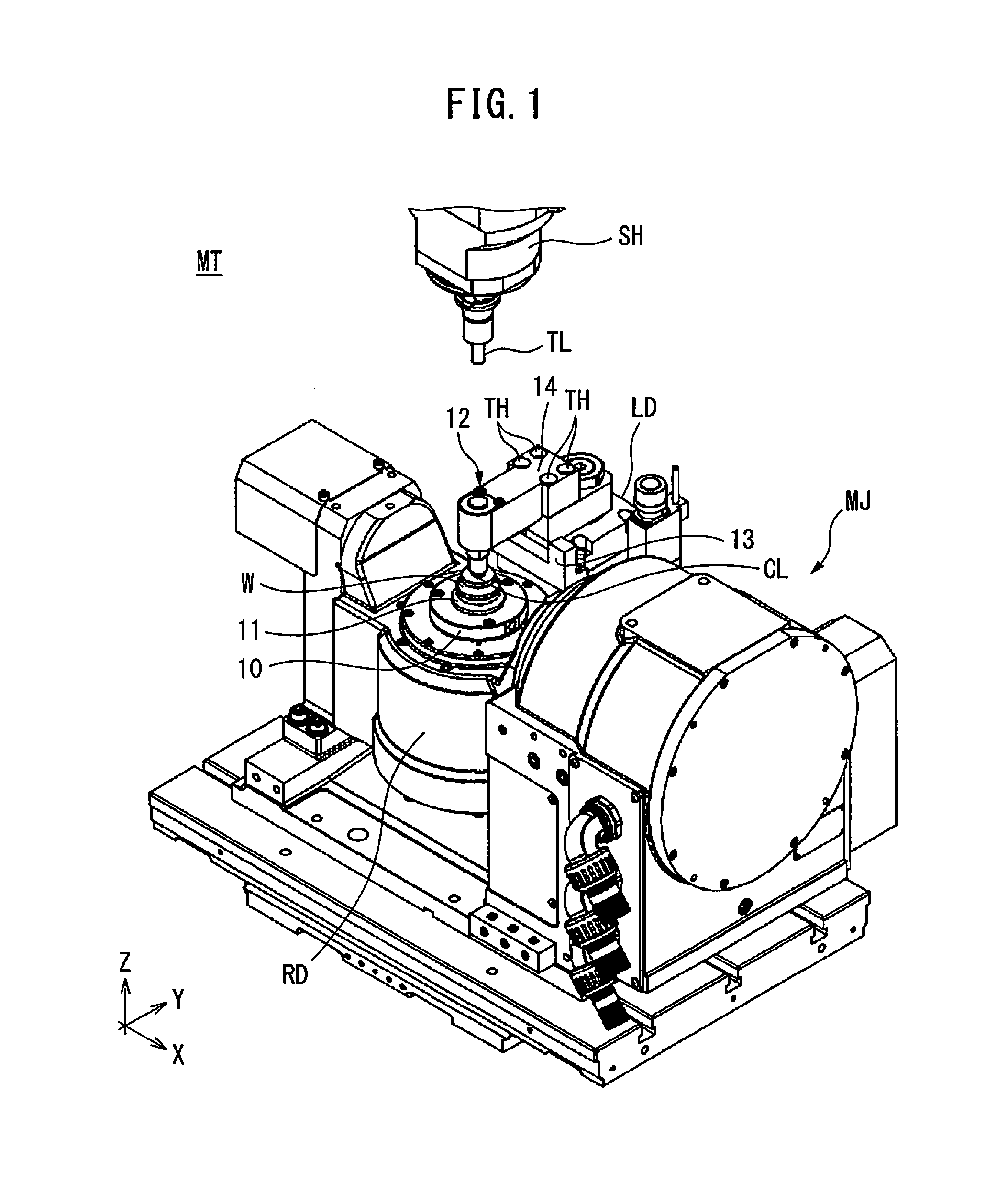
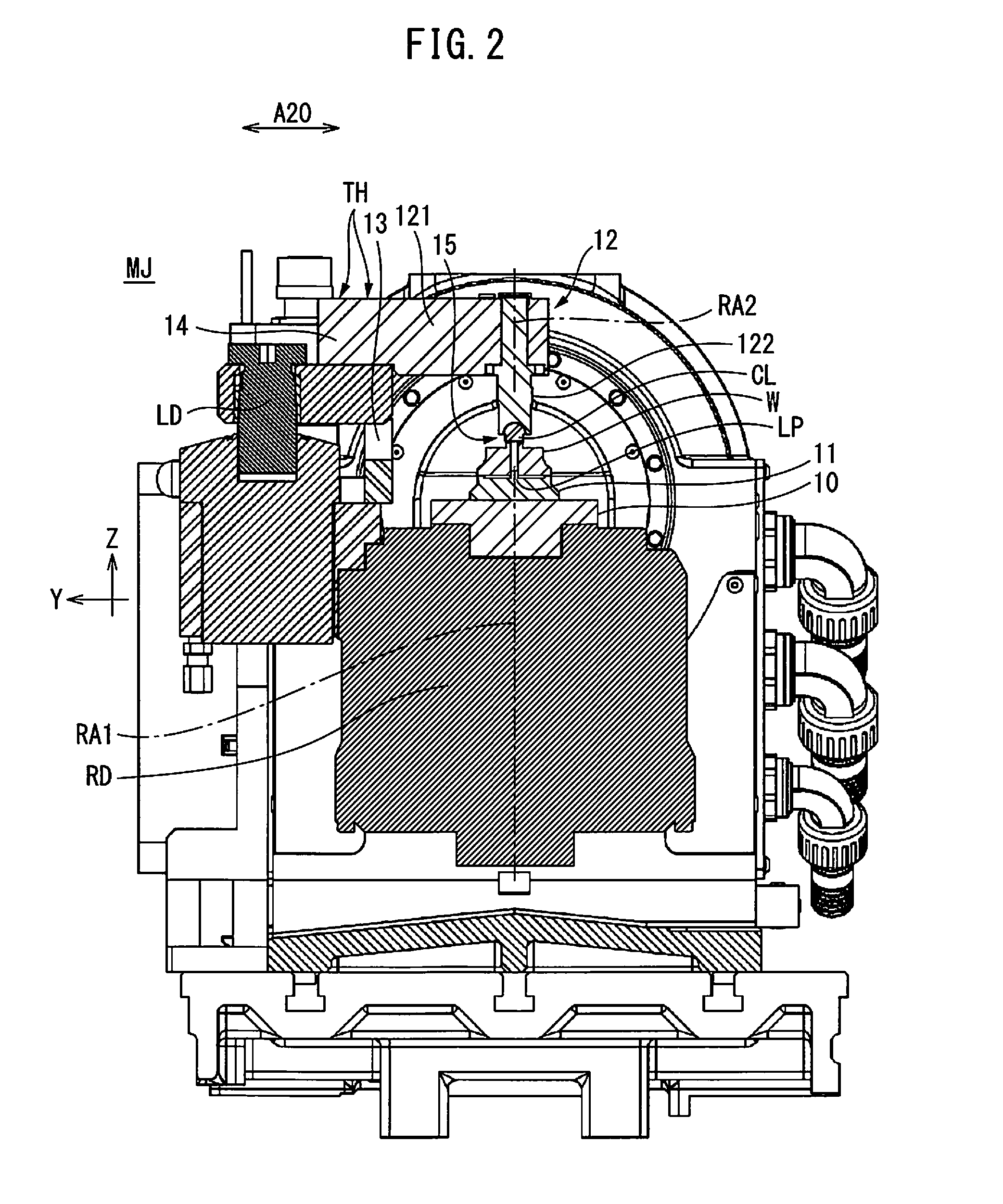
[0022]Referring to FIG. 1 to FIG. 4, a machining jig of a machine tool according to one embodiment of the present invention will be explained. FIG. 1 is a perspective view of an illustrative machine tool MT which is provided with a machining jig of the present embodiment. The machine tool MT of the present example is a so-called rotary table type machine tool and is provided with a spindle head SH which is moved by a servo motor or other drive means in the Z-direction of FIG. 1, and a machining jig MJ which rotatably supports a workpiece W about a predetermined rotation axis. As shown in FIG. 1, the spindle head SH has an end mill or other of various cutting tools TL attached to it. The machine tool MT is configured to machine...


PUM


Abstract

A machining jig for rotatably supporting a workpiece comprising: a rotary drive part which rotates a seating part about a rotation axis, a clamp arm which has a rotary type clamp member which cooperates with the seating part to fasten a workpiece at a position separated from the seating part in a direction along the rotation axis of the seating part, a linear drive part which moves the clamp arm in a direction along a rotation axis, a position adjusting part which adjusts a position of the clamp arm in a plane intersecting the rotation axis, and a tilt adjusting part which adjusts a tilt of the clamp member so that a rotation axis of the clamp member becomes parallel with the rotation axis of the seating part.

Description

BACKGROUND OF THE INVENTION[0001]1. Field of the Invention[0002]The present invention relates to a machining jig which rotatably supports a workpiece with respect to a tool of a machine tool, and to a machining system.[0003]2. Description of the Related Art[0004]In general, a machine tool with a rotating table where a workpiece to be machined is placed is called a “rotary table type machine tool”. In order to precisely machine a workpiece using a rotary table type machine tool, it is necessary to reliably fasten the workpiece to the table. In relation to this, JP-A-2011-513077 proposes a machine tool with a rotary type support table which has a projection fitted into a center hole of a workpiece from below, and a friction joining type clamping mechanism which applies a pushing force to a top surface of a workpiece placed on the support table so as to strongly hold the workpiece. More specifically, the clamping mechanism of JP-A-2011-513077 is provided with an arm shaped opposing hol...

Claims


Application Information

Patent Timeline
IPC IPC(8): B23C1/14B23Q3/06B23Q17/22B23Q1/26
CPCB23C1/14B23Q1/26B23C2270/08B23Q17/2291B23C2260/04B23Q3/069B23Q1/25B23Q3/06B23Q15/22Y10T409/306048Y10T409/30616Y10T409/305824Y10T82/2571Y10T29/5109Y10T483/16Y10T82/2511Y10T29/5114B23Q1/32B23Q1/5406B23Q7/00B23B3/065
Inventor OGAWA, KENICHINAGATOMI, TAKASHI
Owner FANUC LTD
Why Eureka
Try Eureka