
Systems and methods for supporting demand paging for subsystems in a portable computing environment with restricted memory resources

a portable computing environment and subsystem technology, applied in the direction of memory adressing/allocation/relocation, instruments, fault response, etc., to achieve the effect of reducing the overhead of paging on the subsystem

Inactive Publication Date: 2015-09-17
QUALCOMM INC
View PDF3 Cites 21 Cited by
  • Summary
  • Abstract
  • Description
  • Claims
  • Application Information

AI Technical Summary

Benefits of technology

The patent text describes a system and method that manages the transfer of pages from a virtual memory space to a physical memory, reducing paging requirements for subsystems in portable computing devices. The system includes a hypervisor and a task scheduler that work together with device drivers to transfer pages and communicate the completion of the transfer to the subsystem. The system can be used on devices with single or multiple channel memory systems. Overall, the system provides a scalable solution for manufacturers to reduce subsystem memory requirements.

Problems solved by technology

However, manufacturers of cellular telephones and other portable computing devices are motivated by power consumption, size, weight and device production costs to identify and implement performance improvements without necessarily increasing the data storage capacity available to the various subsystems implemented in these devices.
Some of these highly integrated systems or subsystems of the portable computing device include a limited number of internal memory circuits to support the various processors.
The introduction of embedded multimedia card (eMMC) based memory, which includes a single port, preempts the use of the conventional controllers using conventional paging methods as many of the controllers cannot support access from multiple processors running in separate execution environments.

Method used


Image

  • Systems and methods for supporting demand paging for subsystems in a portable computing environment with restricted memory resources
  • Systems and methods for supporting demand paging for subsystems in a portable computing environment with restricted memory resources
  • Systems and methods for supporting demand paging for subsystems in a portable computing environment with restricted memory resources

Examples


Embodiment Construction

[0018]The word “exemplary” is used herein to mean “serving as an example, instance, or illustration.” Any aspect described herein as “exemplary” is not necessarily to be construed as preferred or advantageous over other aspects.

[0019]In this description, the term “application” may also include files having executable content, such as: object code, scripts, byte code, markup language files, and patches. In addition, an “application” referred to herein, may also include files that are not executable in nature, such as documents that may need to be opened or other data files that need to be accessed.

[0020]The term “content” may also include files having executable content, such as: object code, scripts, byte code, markup language files, and patches. In addition, “content” referred to herein, may also include files that are not executable in nature, such as documents that may need to be opened or other data files or data values that need to be accessed.

[0021]As used in this description,...


PUM


Abstract

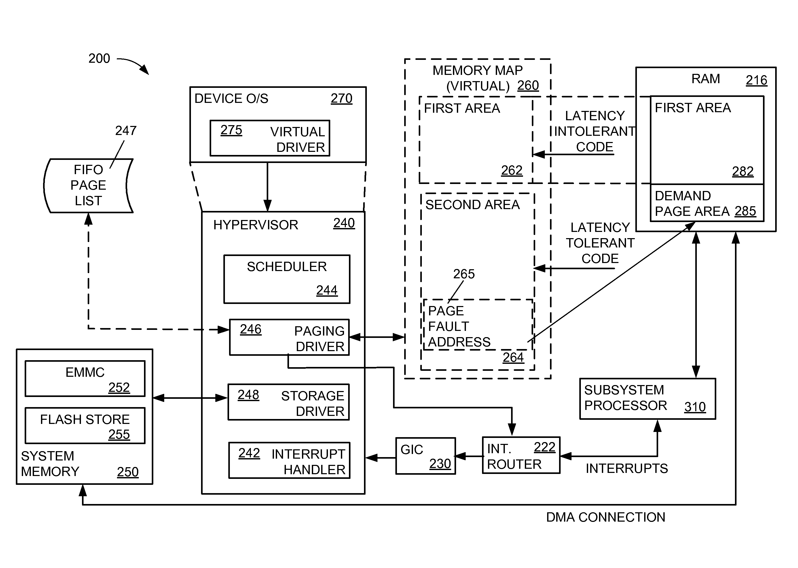
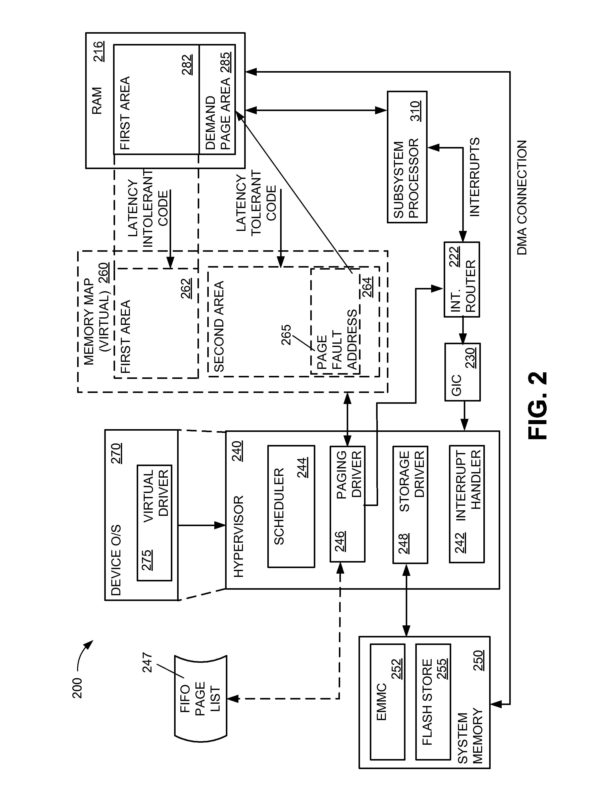
A portable computing device is arranged with one or more subsystems that include a processor and a memory management unit arranged to execute threads under a subsystem level operating system. The processor is in communication with a primary memory. A first area of the primary memory is used for storing time critical code and data. A second area is available for demand pages required by a thread executing in the processor. A secondary memory is accessible to a hypervisor. The processor generates an interrupt when a page fault is detected. The hypervisor, in response to the interrupt, initiates a direct memory transfer of information in the secondary memory to the second area available for demand pages in the primary memory. Upon completion of the transfer, the hypervisor communicates a task complete acknowledgement to the processor.

Description

DESCRIPTION OF THE RELATED ART[0001]Computing devices are ubiquitous. Some computing devices are portable such as smartphones, tablets and laptop computers. In addition to the primary function of these devices, many include elements that support peripheral functions. For example, a cellular telephone may include the primary function of enabling and supporting cellular telephone calls and the peripheral functions of a still camera, a video camera, global positioning system (GPS) navigation, web browsing, sending and receiving emails, sending and receiving text messages, push-to-talk capabilities, etc. As the functionality of such portable computing devices increases, the computing or processing power required and generally the data storage capacity to support such functionality also increases. However, manufacturers of cellular telephones and other portable computing devices are motivated by power consumption, size, weight and device production costs to identify and implement perform...

Claims


Application Information

Patent Timeline
IPC IPC(8): G06F12/10G06F9/455G06F11/16G06F13/28G06F13/24
CPCG06F12/1009G06F13/28G06F13/24G06F2009/45575G06F9/45533G06F2212/403G06F11/1666G06F12/08G06F9/45558G06F2009/45583G06F2212/151G06F2212/171
Inventor NAMPOOTHIRI, SANKARANVALIAPARAMBIL, ARUNSINGH, SUBODHTOUZNI, AZZEDINE
Owner QUALCOMM INC
Learn More