Fiber optic epoxy cutting tool and method of use

Inactive Publication Date: 2015-09-17
ROBICHAUD ROGER E
View PDF9 Cites 7 Cited by
  • Summary
  • Abstract
  • Description
  • Claims
  • Application Information

AI Technical Summary

Benefits of technology

The present invention provides a fiber optic epoxy cutting tool and method of use that eliminates or reduces many conventional processing steps, including cleaving the protruding fiber, smoothing out the protruding fiber stub, and polishing off the epoxy bead and fiber. The cutting tool is designed to be adapted to cut through both the fiber and the hard epoxy that forms a bead at or around the exit hole(s) of the ferrule. By cutting close to the ferrule, the device may advantageously remove a maximum amount of material, which greatly shortens processing. The cutting tool is small, lightweight, battery powered, and easily portable. The cutting tool provides flat, calibrated, and reproducible cuts a fixed distance from the face of the ferrule. The cutting tool may be used with all ferrule or connector materials, including metals, ceramics, and low melting temperature thermoplastics. The cutting tool has an extremely long service lifecycle due to the resiliency of the cutting materials, i.e., diamonds, employed on the surface of the saw blade.

Problems solved by technology

The construction, sometimes referred to as installation, of fiber optic connectors is usually accomplished in a factory environment but it is sometimes necessary to construct, or install, the connectors in the field under less than ideal circumstances.
This method requires an initial investment in several expensive polishing machines, ongoing consumables expenses, such as polishing film and other supplies, and skilled labor to operate production lines.
This method is expensive and complex.
This equipment is expensive, complex and bulky.
As a result, use of the equipment is limited to high volume factory environments.
Further complicating matters is the fact that the high energy of the focused laser beam can damage and melt the polymer material of some ferrule thus limiting its application.
In addition, there are user safety concerns due to the toxicity of the vaporized material that is generated and high power of the laser beam.
Polishing is tedious and labor intensive due to the many steps and the amount of time required in removing the epoxy bead and polishing the fiber flush with ferrule face.

Method used


Image

  • Fiber optic epoxy cutting tool and method of use
  • Fiber optic epoxy cutting tool and method of use
  • Fiber optic epoxy cutting tool and method of use

Examples


Embodiment Construction

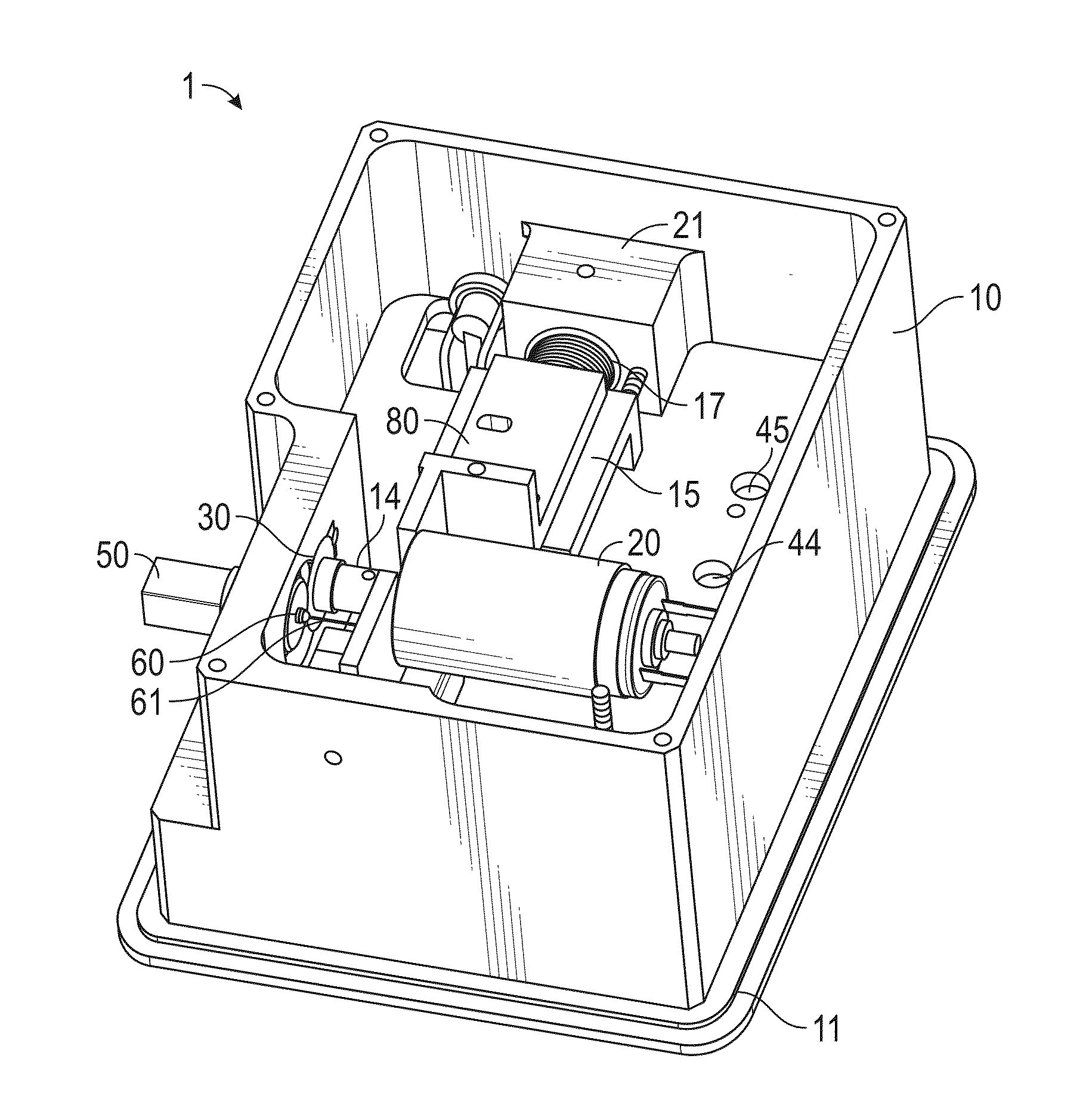
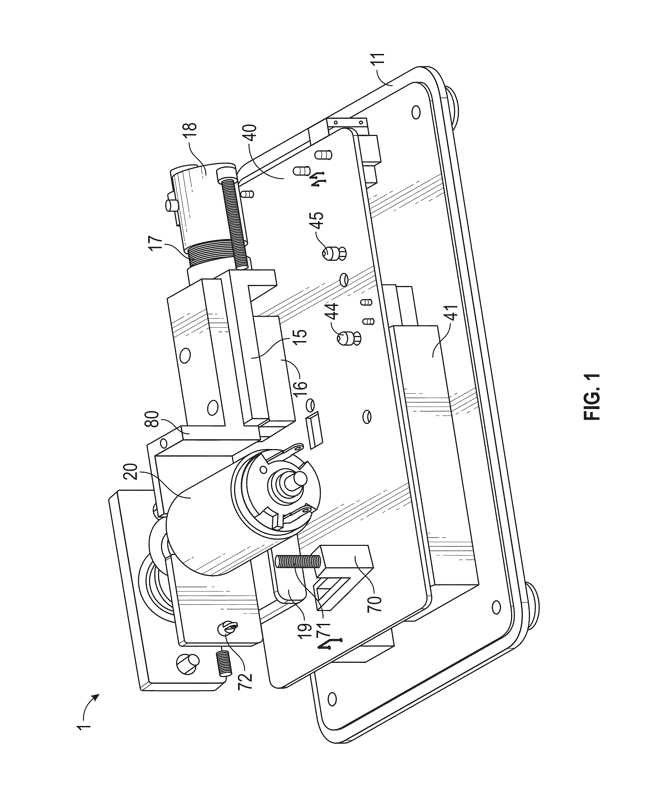
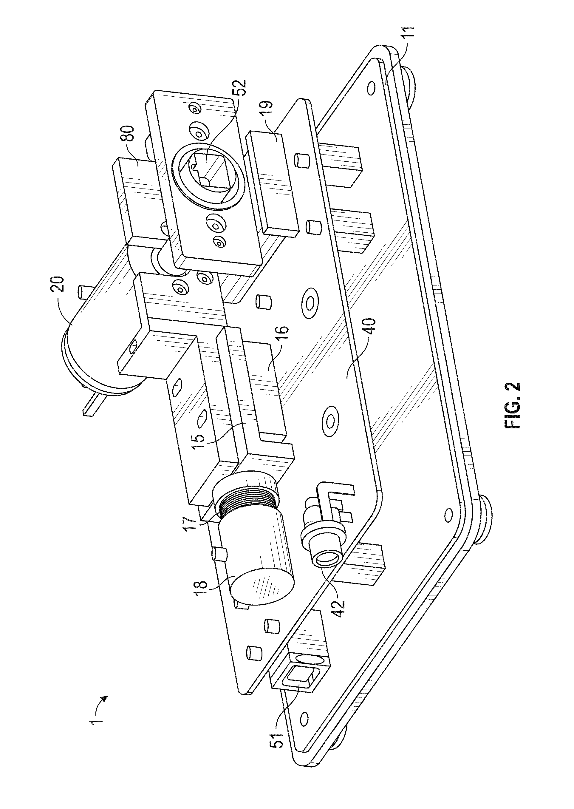
[0033]The present invention will now be described more fully hereinafter with reference to the accompanying drawings, in which preferred embodiments of the invention are shown. This invention may, however, be embodied in many different forms and should not be construed as limited to the embodiments set forth herein. Rather, these embodiments are provided so that this disclosure will be thorough and complete, and will fully convey the scope of the invention to those skilled in the art. Those of ordinary skill in the art realize that the following descriptions of the embodiments of the present invention are illustrative and are not intended to be limiting in any way. Other embodiments of the present invention will readily suggest themselves to such skilled persons having the benefit of this disclosure. Like numbers refer to like elements throughout.

[0034]Although the following detailed description contains many specifics for the purposes of illustration, anyone of ordinary skill in th...


PUM

PropertyMeasurementUnit
Grain sizeaaaaaaaaaa

Abstract

A cutting tool comprising a housing, an adapter carried by the housing configured to receive and carry a connector or a ferrule, a slide, a saw assembly carried by the slide and comprising a motor bracket, a first motor attached to the motor bracket, and a saw blade operably connected to the first motor. The cutting tool also includes a second motor operably connected to the slide, a controller, and a power source. The first motor is operable to rotate the saw blade. The second motor is operable to translate the saw blade along a cutting path so as to interface with and cut at least one of a ferrule, a fiber, and an epoxy bead of the connector or the ferrule carried by the adapter. The saw blade may further comprise a coating comprising diamond crystals having an edge length within the range from 1 μm to 25 μm.

Description

FIELD OF THE INVENTION [0001]The present invention relates to fiber optic epoxy cutting tool systems and methods for using a fiber optic epoxy cutting tool.BACKGROUND [0002]Fiber optic cables are being installed worldwide to respond to the huge demand for high-speed communication technologies. Each installed cable can enclose hundreds of individual fibers, all of which must be connected. The construction, sometimes referred to as installation, of fiber optic connectors is usually accomplished in a factory environment but it is sometimes necessary to construct, or install, the connectors in the field under less than ideal circumstances.[0003]Fiber optic connectors can be either a single fiber connector or a multiple fiber connector. Single fiber connectors enclose a precision cylindrical ferrule usually made of ceramic but can also be metal or polymer plastics. The bare fiber is threaded through the center axial hole of the ferrule and secured with epoxy. After curing, the protruding...

Claims


Application Information

Patent Timeline
IPC IPC(8): G02B6/38B26D1/18
CPCB26D1/18G02B6/3898G02B6/3863G02B6/25B26D3/16B26D2001/002Y10T83/778
Inventor ROBICHAUD, ROGER E.
Owner ROBICHAUD ROGER E
Why Eureka
Try Eureka