
Plugged honeycomb structure and manufacturing method of the same

a technology of plugged honeycomb and manufacturing method, which is applied in the direction of domestic applications, machines/engines, chemical/physical processes, etc., can solve the problems of disadvantageous expansion of initial pressure loss of plugged honeycomb structure (dpf), and the performance of the trapping layer deteriorates, so as to effectively inhibit the deterioration of the performance of the trapping layer. , the effect of high heat capacity

Active Publication Date: 2015-09-17
NGK INSULATORS LTD
View PDF8 Cites 13 Cited by
  • Summary
  • Abstract
  • Description
  • Claims
  • Application Information

AI Technical Summary

Benefits of technology

The present invention provides a plugged honeycomb structure with increased heat capacity and lowered pressure loss during regeneration. The structure includes a porous partition wall base material and a trapping layer, which helps inhibit the rise of pressure loss due to deposition of particulate matter. The structure is also excellent in thermal shock resistance and can effectively inhibit temperature rise during regeneration. The manufacturing method of the structure is easy and cost-effective. Overall, the invention provides a solution to inhibit performance deterioration and temperature rise in filters such as DPF.

Problems solved by technology

In the plugged honeycomb structure including the trapping layer, when a temperature in the DPF excessively rises, the trapping layer having a large specific surface area, a catalyst loaded onto the trapping layer and ash or the like discharged from an engine react, and there is a possibility that a problem occurs that a performance of the trapping layer deteriorates.
However, when the porosity of the partition wall base material is excessively lowered, an initial pressure loss of the plugged honeycomb structure (i.e., the DPF) disadvantageously enlarges.

Method used


Image

  • Plugged honeycomb structure and manufacturing method of the same
  • Plugged honeycomb structure and manufacturing method of the same
  • Plugged honeycomb structure and manufacturing method of the same

Examples


example 1

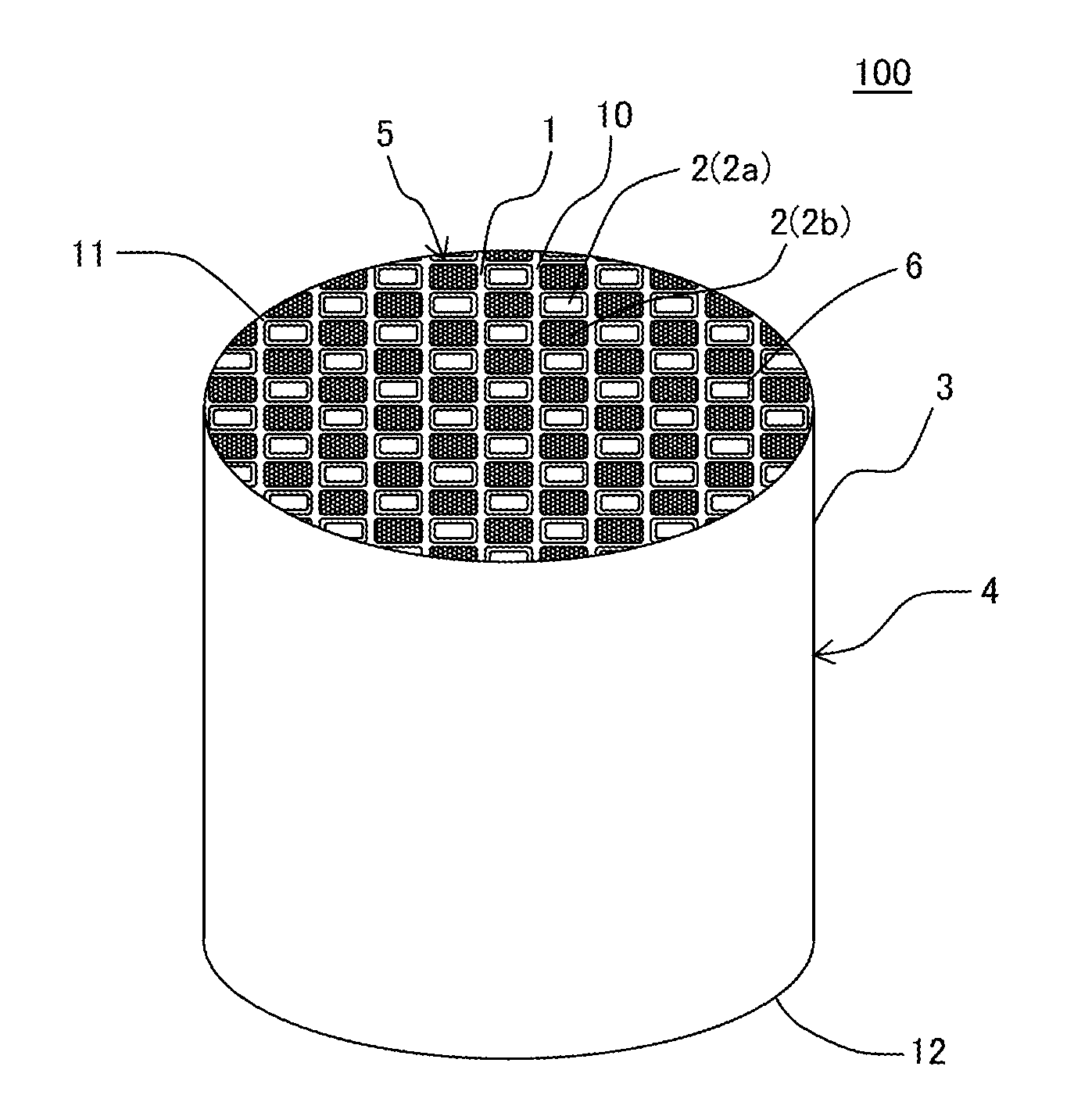
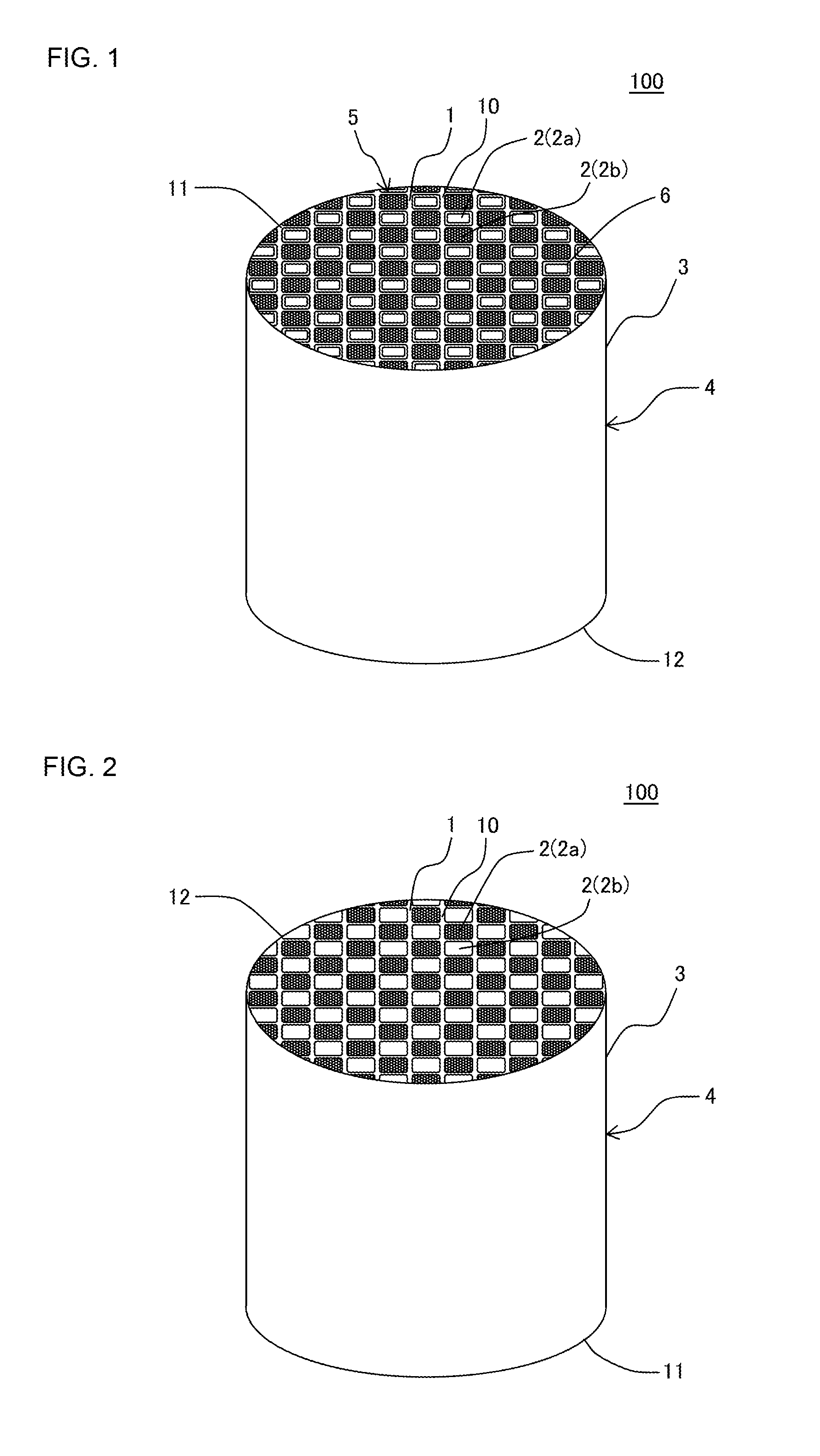
[0119]In Example 1, a forming raw material to prepare a honeycomb structure body was first prepared. The fonning raw material was prepared by adding an appropriate amount of water to powder obtained by mixing 3900 g of α-Al2O3 powder, 750 g of TiO2 powder, 300 g of talc powder, 50 g of mica powder, 50 g of starch, and 200 g of methylcellulose. An average particle diameter of the α-Al2O3 powder was 42 μm. An average particle diameter of the TiO2 powder was 0.4 μm. An average particle diameter of the talc powder was 11 μm. An average particle diameter of the mica powder was 42 μm.

[0120]Next, the obtained forming raw material was kneaded with a kneader and then kneaded with a vacuum pugmill to form a kneaded material. Next, the obtained kneaded material was extruded to prepare a honeycomb formed body. As to the honeycomb formed body after fired, a thickness of a partition wall base material became 300 μm and a cell density became 46.5 cells / cm2. A cell shape of the honeycomb formed bod...

example 2

[0151]In Example 2, first, the procedures of Example 1 were repeated to prepare a honeycomb dried body. Furthermore, the procedures of Example 1 were repeated to cut the obtained honeycomb dried body so that a length of the honeycomb dried body in a cell extending direction was a predetermined length.

[0152]Next, a plugging material was charged into open ends of cells only to a first end face in the first end face and a second end face of the honeycomb dried body.

[0153]Next, a film was attached to the second end face of the honeycomb dried body to mask the second end face and holes were made in portions of this mask in which cells other than the cells including the plugging material charged thereinto in the first end face were disposed. In consequence, the cells into which the plugging material was charged in the first end face were closed with the plugging material and the mask in the first end face and the second end face, and the other cells were allowed to communicate from the fi...

example 3

[0156]The procedures of Example 2 were repeated except that a ratio of a prepared membrane length of a trapping layer was 80% as shown in Table 2, to prepare a plugged honeycomb structure. Specifically, in Example 3, a masked honeycomb dried body was vertically disposed so that a first end face was positioned on a vertically upper side and slurry including a trapping layer forming raw material was charged into a region of 80% of a cell extending direction from the side of a second end face (the masked end face) positioned on a vertically lower side. In Example 3, the trapping layer was formed in the region of 80% of the cell extending direction from the end face on an outlet side of a honeycomb structure body by such a method as described above.


PUM

PropertyMeasurementUnit
mass %aaaaaaaaaa
porosityaaaaaaaaaa
pore diameteraaaaaaaaaa

Abstract

There is disclosed a plugged honeycomb structure. A plugged honeycomb structure includes a tubular honeycomb structure body having partition walls including a porous partition wall base material defining a plurality of cells which become through channels for a fluid and extend from a first end face to a second end face, and a porous trapping layer disposed on the surface of the partition wall base material; and plugging portions disposed in open ends of predetermined cells in the first end face and open ends of residual cells in the second end face, and the partition wall base material is constituted of a porous body including α-Al2O3 as a main phase and further including aluminum titanate and glass.

Description

[0001]The present application is an application based on JP2014-52421 filed with Japan Patent Office on Mar. 14, 2014, the entire contents of which are incorporated herein by reference.BACKGROUND OF THE INVENTION[0002]1. Field of the Invention[0003]The present invention relates to a plugged honeycomb structure and a manufacturing method of the plugged honeycomb structure, and more particularly, it relates to a plugged honeycomb structure which can effectively inhibit a rise of a pressure loss generated due to deposition of particulate matter on partition walls while lowering the highest temperature during regeneration, when the plugged honeycomb structure is used as a filter such as a DPF, and a manufacturing method of the plugged honeycomb structure.[0004]2. Background Art[0005]An exhaust gas discharged from an internal combustion engine such as a diesel engine, each type of combustion device or the like includes a large amount of particulate matter (hereinafter also referred to as...

Claims


Application Information

Patent Timeline
Patent Type & Authority Applications(United States)
IPC IPC(8): F01N3/022B01D46/00B01D53/94
CPCF01N3/0222B01D2258/01B01D46/0001B01D53/94C04B35/117C04B38/0006C04B2201/30C04B2235/3217C04B2235/3232C04B2235/3234C04B2235/3472C04B2235/3481C04B2235/349C04B2235/36C04B2235/5436C04B2235/5445C04B2235/606C04B2235/80B01D46/2474B01D46/2429C04B2235/9607C04B2235/76B01D46/24492B01D46/24491B01D46/24494B01D46/2476B01D46/2482B01J35/56B01J35/60C04B38/0054C04B38/0074
Inventor KIKUCHI, YOSHIOSUZUKIISHIKAWA, MASAKI
Owner NGK INSULATORS LTD
Learn More