
Tool Head

a tool head and tool head technology, applied in the field of tool heads, can solve the problems of insufficient strength of the head to undergo a relatively large toque and be susceptible to breakage, and achieve the effect of enduring high torque transmission

Inactive Publication Date: 2015-09-17
HONG ANN TOOL INDS
View PDF1 Cites 8 Cited by
  • Summary
  • Abstract
  • Description
  • Claims
  • Application Information

AI Technical Summary

Benefits of technology

The present invention relates to a tool head that can withstand high torque transmission and is assembled together with a driving component, connecting component, and spacer, which results in a tight-fit and fit region, preventing damage to the components and ensuring alignment in assembly. Additionally, the invention improves the connection between the driving component and the connecting component to prevent detachment and rotation of the connecting component.

Problems solved by technology

Unfortunately, such conventional tool head is not strong enough to undergo a relatively large toque when the connected tool or tool handle starts turning it, and is also susceptible to breakage when being rotated rapidly.

Method used


Image

  • Tool Head
  • Tool Head
  • Tool Head

Examples


Embodiment Construction

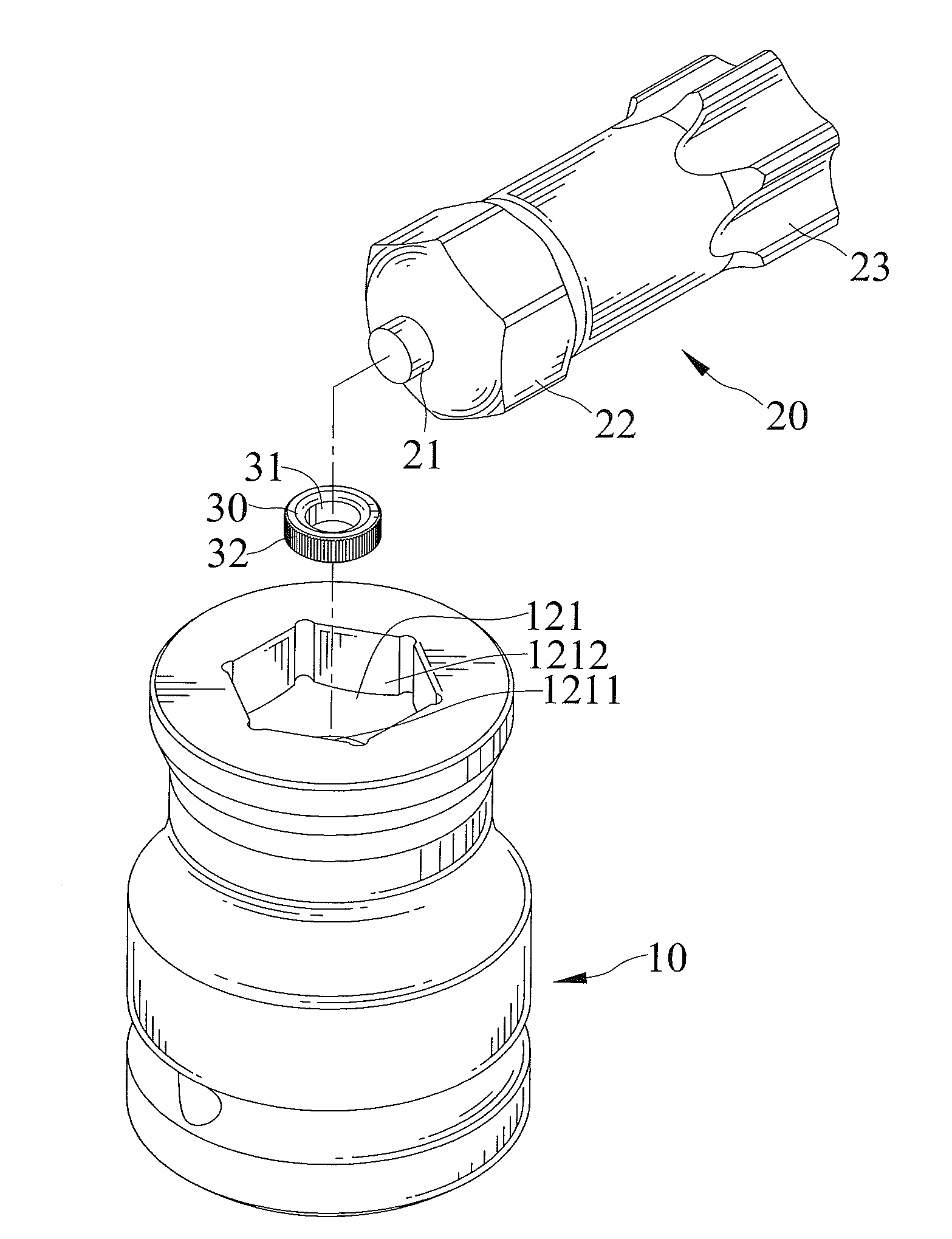
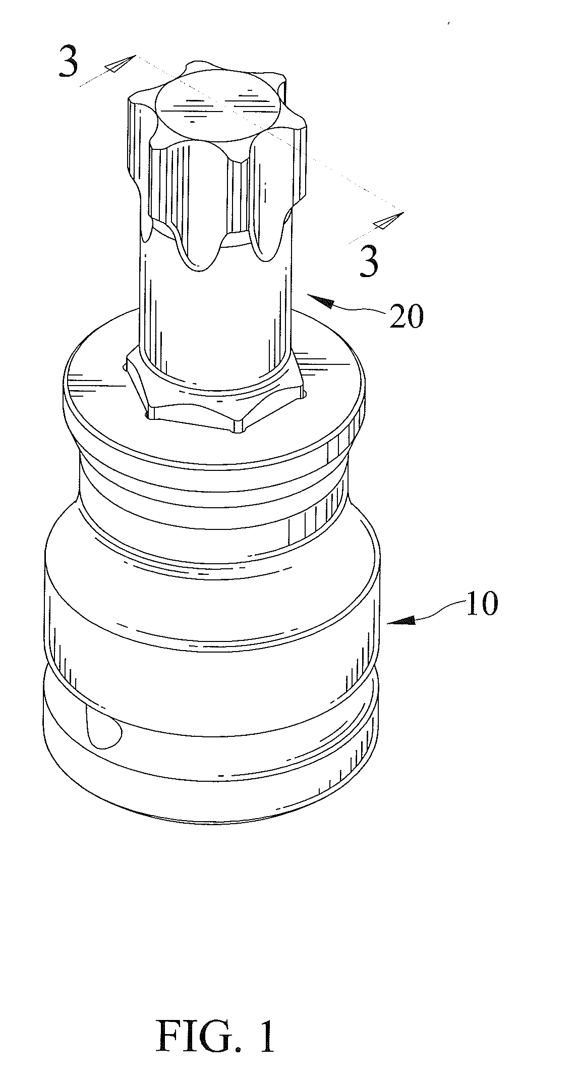
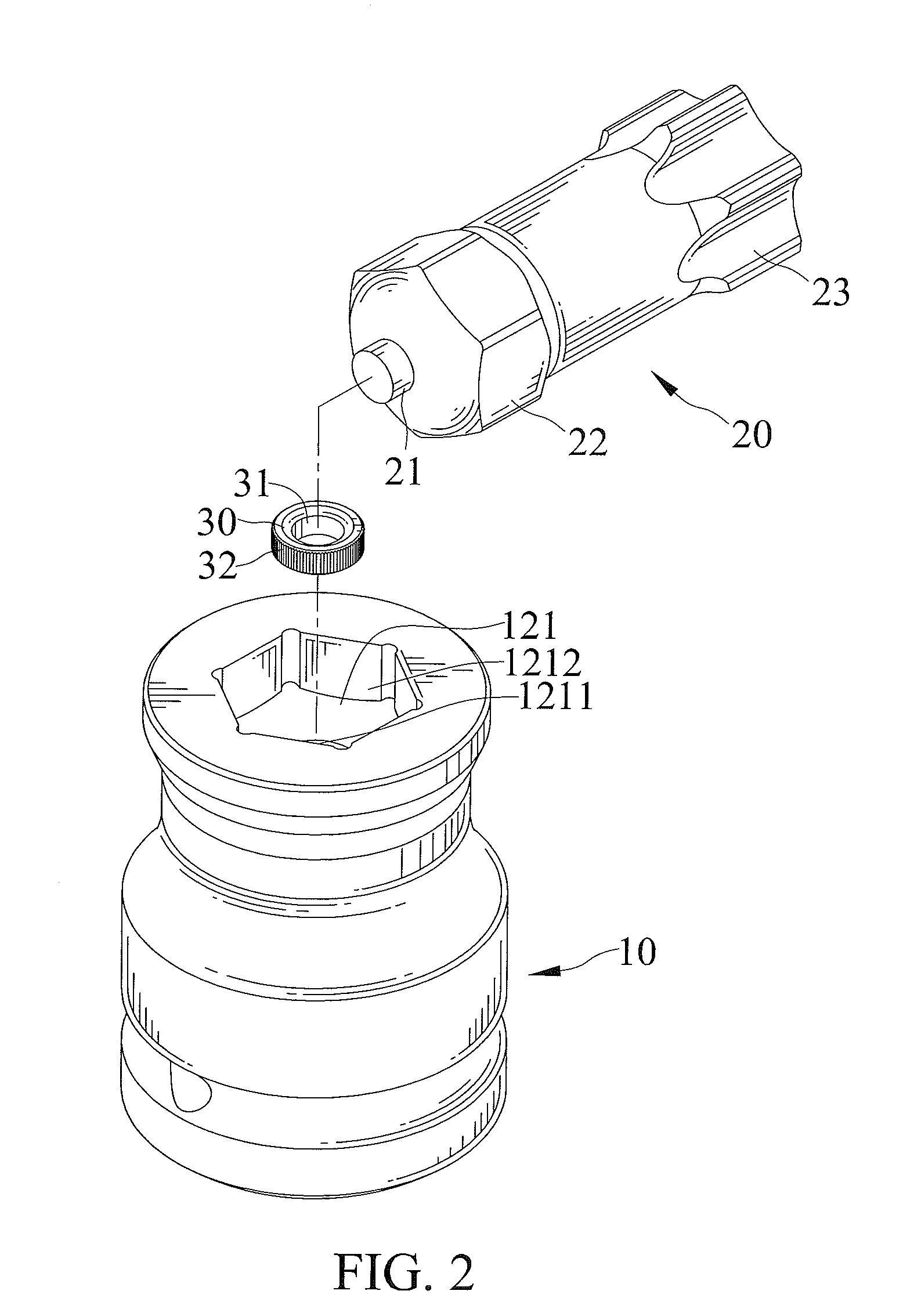
[0029]FIGS. 1 through 5 show a tool head in accordance with a first embodiment of the present invention. The tool head is usable as an adaptor such that a tool is connectable to an end of the tool head and an object to be driven is connectable to another end of the tool head, respectively. The tool can be a power tool which can rotate the tool head in a rapid motion. The power tool includes a pneumatic tool or an electric tool.

[0030]The tool head includes a connecting component 10, a driving component 20, and a spacer 30 formed separately. The connecting component 10, the driving component 20, and the spacer 30 are assembled together.

[0031]The connecting component 10 has two opposite distal ends. The connecting component 10 extends in a lengthwise direction from a first distal end to a second distal end thereof. The connecting component 10 includes the first distal end thereof forming a connecting end 11 and the second distal end thereof forming a receiving end 12, respectively. The...


PUM


Abstract

A tool head includes a connecting component, a driving component, and a spacer assembled together. The connecting component includes a receiving end forming a first compartment and a second compartment. The driving component includes an engaging end forming a first engaging section and a second engaging section. The tool head has a tight-fit region in which the first engaging section and the spacer are tightly fit within the first compartment and a fit region in which the second engaging section is retained within the second compartment.

Description

CROSS REFERENCE TO RELATED APPLICATION[0001]The present application is a continuation-in-part application of U.S. patent application Ser. No. 13 / 705,263 filed on Dec. 5, 2012, of which the disclosure is incorporated herein.BACKGROUND OF THE INVENTION[0002]1. Field of the Invention[0003]The present invention relates to a tool head and, particularly, to a tool head not susceptible to breakage easily.[0004]2. Description of the Related Art[0005]A conventional tool head includes a connecting end for connecting the tool head to a tool or a tool handle and a driving end for driving an object to be driven. Generally, the conventional tool head is a one-piece structure and is made of relatively harder material to withstand the object to be driven and which wears the tool head when the tool head is driven to drive the object to be driven.[0006]Some conventional tool heads have a relative longer longitudinal length for specific tools or tool handles, and are made in two pieces in order to sav...

Claims


Application Information

Patent Timeline
Patent Type & Authority Applications(United States)
IPC IPC(8): B25B23/00
CPCB25B23/0035
Inventor SU, CHENG-WEI
Owner HONG ANN TOOL INDS
Learn More