Catalyst structure for exhaust gas cleaning

a catalyst and exhaust gas technology, applied in physical/chemical process catalysts, metal/metal-oxide/metal-hydroxide catalysts, separation processes, etc., can solve the problems of increasing pressure loss and deteriorating denitrification efficiency, and achieve low pressure loss, high denitrification efficiency per weight of catalyst, and effect of imparting turbulence to gas flow

Active Publication Date: 2015-09-17
MITSUBISHI POWER LTD
View PDF2 Cites 1 Cited by
  • Summary
  • Abstract
  • Description
  • Claims
  • Application Information

AI Technical Summary

Benefits of technology

[0018]The catalyst structure according to the present invention is capable of effectively imparting turbulence to the gas flow with a small pressure loss. As a result, the denitrification efficiency per weight of the catalyst is high. In the catalyst structure according to the present invention, when the baffle part in one plate-like catalyst element is arranged at the same position as that of the baffle part in an adjacent superimposed plate-like element as viewed from the direction normal to the flat part, turbulence can be effectively imparted to the gas flow with a small pressure loss and thus the amount of exhaust gas passing through the catalyst structure without contact with the catalyst can be significantly decreased.
[0019]When a hole passing through the flat part from the front surface to the rear surface is formed in a section having the baffle part, some of the gas colliding with the baffle part passes the through-hole and thus the pressure loss can be significantly decreased.
[0020]Since the denitrification performance can be improved with the same amount of the catalyst as in the present invention, the amount of the catalyst used can be significantly decreased. In addition, according to the exhaust gas conditions of an actual machine, the condition for disposing the baffle part can be freely set and thus it is possible to cope with a wide range of exhaust gas.

Problems solved by technology

Since the exhaust gas from the thermal power plants using coal and heavy oil as fuels contains a large amount of soot and dust, a denitrification catalyst becomes clogged, which is likely to incur an increase in pressure loss and a deterioration in denitrification efficiency over time.

Method used


Image

  • Catalyst structure for exhaust gas cleaning
  • Catalyst structure for exhaust gas cleaning
  • Catalyst structure for exhaust gas cleaning

Examples


example 1

[0046]10 kg of titanium oxide, 2 kg of ammonium molybdate ((NH4)6.Mo7O24.4H2O), 1 kg of ammonium metavanadate, and 1 kg of oxalic acid were mixed and kneaded by a kneader for 1 hour while water was added to obtain a paste. Then, 2 kg of silica-alumina-based inorganic fiber was added to the paste and the mixture was further kneaded for 30 minutes to obtain a catalyst paste with a water content of about 30%. The obtained paste was applied to the mesh and surface of a long strip-like metal lath base having a width of 500 mm, made of SUS430, prepared in advance using a pair of rolling rollers, and thus a flat plate-like catalyst element having a long strip shape and a thickness of 0.7 mm was obtained. As shown in FIG. 5, after wavy spacer parts (height h=6 mm) were formed using a pressing machine in the catalyst element, a plate-like catalyst having a long strip shape was obtained. After that, the plate-like catalyst having a long strip shape was cut to a width of 150 mm and length of 6...

example 2

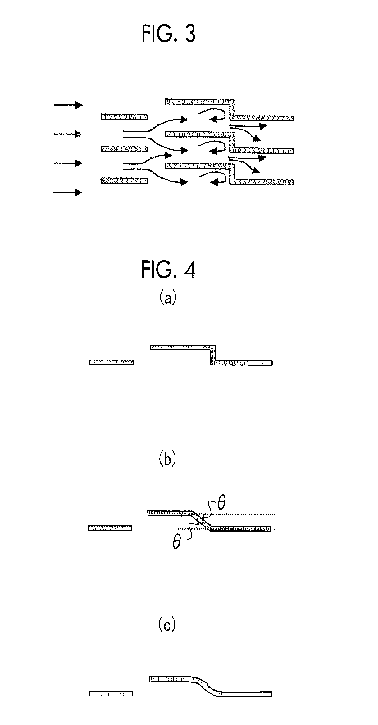
[0047]A catalyst unit B in which the directions of the baffle parts formed in each catalyst element, which was formed by superimposing the catalyst elements (2) obtained in Example 1 as shown in FIG. 2(b), were the same was prepared. The gas was caused to flow in the direction shown in FIG. 2(b).

examples 3 and 4

[0048]Catalyst units C and D were prepared in the same manner as in Example 2 except that the top plate length d of the reversed L-shaped baffle part was respectively changed to 10 mm and 30 mm.


PUM

PropertyMeasurementUnit
lengthaaaaaaaaaa
thicknessaaaaaaaaaa
temperatureaaaaaaaaaa

Abstract

A catalyst structure for exhaust gas cleaning obtained by superimposing flat plate-like catalyst elements composed of a flat part, which is a main structural part, and a linear spacer part composed of raised strips and recessed strips so that a gas flow channel is ensured along the lengthwise direction of the spacer part, wherein the flat part has at least one baffle part composed of a leg plate erectly provided on the flat part with a height that is less than that of the spacer part with reference to the flat part, and a top plate disposed substantially parallel to the flat part from the upper end of the leg plate. Turbulence can be imparted by the baffle part to gas that flows to the gas flow channel.

Description

TECHNICAL FIELD[0001]The present invention relates to a catalyst structure for exhaust gas cleaning. More specifically, the present invention relates to a catalyst structure for exhaust gas cleaning which is suitably used in a denitrification apparatus for removing nitrogen oxides in a boiler exhaust gas and obtained by superimposing flat plate-like catalyst elements so as to ensure a gas flow channel.BACKGROUND ART[0002]Nitrogen oxides (NOx) in gases discharged from thermal power plants, various kinds of factories, automobiles and the like are substances causing photochemical smog and acid rain. As a nitrogen oxide removing technology, an exhaust gas denitrification process by selective catalytic reduction reaction using ammonia (NH3) as a reducing agent is known and is widely used mainly in thermal power plants and the like. Since the exhaust gas from the thermal power plants using coal and heavy oil as fuels contains a large amount of soot and dust, a denitrification catalyst bec...

Claims


Application Information

Patent Timeline
Patent Type & Authority Applications(United States)
IPC IPC(8): B01D53/86B01J23/28
CPCB01D53/8631B01J23/28B01D2255/904B01D2255/30B01D2255/20723B01D2255/20707B01D2255/2092B01D2255/20769B01D53/88B01J2523/00
Inventor KAI, KEIICHIROKATO, YASUYOSHI
Owner MITSUBISHI POWER LTD
Why Eureka
Try Eureka